


Motor Operated Valve: Types, Working Principle & Selection Guide
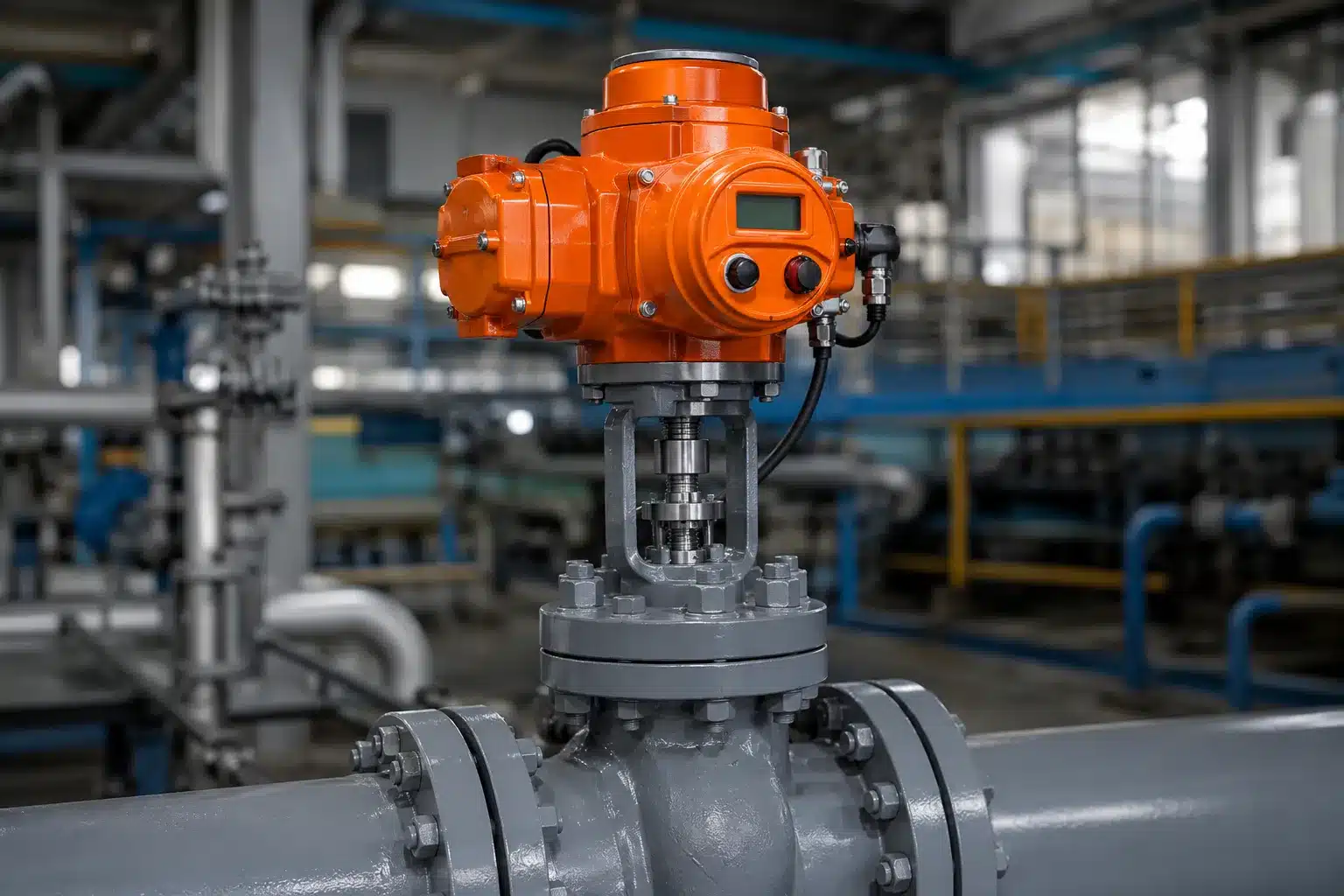
A motor operated valve (MOV) is an industrial valve assembly driven by an electric motor to control, isolate, or regulate fluid flow. By combining an industrial valve with an electric actuator, MOVs enable automated pipeline operation, remote control, and integration with industrial automation systems.
Motor operated valves are widely used in water treatment, power generation, oil and gas, chemical processing, HVAC, and manufacturing. Common configurations include motor operated ball valves, butterfly valves, gate valves, and globe valves, each designed for different operating movements and process requirements.
Electric Motor
Multi / Part / Linear Turn
On/Off & Modulating
Industrial Automation
What Is a Motor Operated Valve?
A motor operated valve is an electrically driven valve used to open, close, or position a pipeline flow-control device. It uses an electric motor and mechanical transmission system to generate the torque or thrust required to move the valve.
Unlike manually operated valves, an MOV can receive commands from a local control station, PLC, DCS, or SCADA system. Depending on its actuator and valve design, it can perform automatic isolation, remote switching, or modulating flow control.

Motor Operated Valve Meaning and Terminology
The abbreviation MOV stands for Motor Operated Valve. In industrial specifications, the term generally refers to a valve assembly operated by an electric motor-driven actuator. You may also encounter the terms electric actuated valve, electrically operated valve, and motorized valve.
These expressions are often used interchangeably in commercial applications, although their technical scope can differ. Understanding the terminology helps engineers identify the correct equipment when preparing specifications or sourcing industrial valves.
| Term | Meaning | Tipik Uygulama |
|---|---|---|
| Motor Operated Valve (MOV) | A valve assembly driven by an electric motor and transmission mechanism. | Industrial pipeline isolation and automation. |
| Elektrikle Çalışan Vana | A valve equipped with an electric actuator. | Automated shutoff and flow control. |
| Motorlu Vana | A common commercial term for an electrically driven valve. | Industrial and commercial systems. |
| Solenoid Valf | A valve operated by electromagnetic force from a solenoid coil. | Fast switching and smaller fluid-control circuits. |
A key distinction is that a motor operated valve uses an electric motor and typically a reduction gearbox, whereas a solenoid valve uses electromagnetic actuation. Their operating mechanisms, torque capabilities, and suitable applications are different.
How Does a Motor Operated Valve Work?
The working principle of a motor operated valve is based on converting electrical energy into controlled mechanical movement. When an operating command is received, the actuator drives the valve through a mechanical transmission system until the required position is reached.
The operating sequence of a typical electric motor operated valve consists of five main stages:
- 01
Command Input
A local switch, PLC, DCS, or remote control system sends an open, close, or positioning command.
- 02
Motor Activation
The actuator control circuit energizes the electric motor and starts mechanical movement.
- 03
Torque Transmission
The reduction gearbox increases available output torque and transfers movement to the valve stem or shaft.
- 04
Valve Movement
The valve opens, closes, or moves toward the required intermediate position.
- 05
Konum Geri Bildirimi
Limit switches and position sensors help confirm the required operating position.
During operation, torque switches and protective circuits may monitor mechanical loading and stop the motor when configured limits are reached. This helps prevent excessive force from damaging the valve stem, seats, gearbox, or actuator.
Intelligent motor operated valve actuators may also monitor motor current, operating temperature, torque, running time, and switching frequency. These functions provide useful information for industrial maintenance and diagnostics.
Main Components of a Motor Operated Valve
An industrial MOV consists of several mechanical, electrical, and control components. Their coordination determines the operating accuracy, mechanical reliability, and service life of the complete valve assembly.
| Component | Main Function |
|---|---|
| Industrial Valve Body | Controls, isolates, diverts, or regulates the process medium. |
| Electric Motor | Converts electrical energy into mechanical movement. |
| Reduction Gearbox | Reduces output speed and increases available operating torque. |
| Output Drive | Transfers torque or thrust to the valve stem or shaft. |
| Limit Switches | Detect configured open and closed positions. |
| Torque Protection | Monitors mechanical load and protects the valve and actuator. |
| Control Circuit | Processes operating commands and controls motor operation. |
| Position Indicator | Displays the current valve position locally or electronically. |
| Manual Override | Provides an alternative means of operation where equipped. |
| Communication Module | Supports PLC, DCS, SCADA, and industrial network integration. |
Types of Motor Operated Valves
Motor operated valves are classified according to the movement produced by the electric actuator. The three main configurations are multi-turn, part-turn, and linear actuation. The appropriate type depends on valve construction, operating torque or thrust, and the required control function.
| Actuator Type | Movement | Compatible Valve Types | Typical Duty |
|---|---|---|---|
| Multi-Turn | Multiple rotations of the output shaft. | Gate valves, globe valves. | Pipeline isolation and stem-driven operation. |
| Part-Turn | Limited rotation, commonly 90 degrees. | Ball valves, butterfly valves, plug valves. | Switching, isolation, and selected modulation. |
| Linear | Straight-line movement over a defined stroke. | Globe control valves and compatible linear valves. | Axial thrust and controlled positioning. |
Multi-Turn Motor Operated Valves
Multi-turn electric actuators rotate their output shaft through several complete revolutions. The movement is transferred to a threaded valve stem, allowing the valve to travel between open and closed positions.
This configuration is commonly used for motor operated gate valves and globe valves. Depending on the valve design, the actuator may include a hollow output shaft to accommodate a rising stem.
Part-Turn Motor Operated Valves
Part-turn electric actuators produce a limited angular movement. Most quarter-turn designs rotate approximately 90 degrees to operate the valve between fully open and fully closed positions.
Motor operated ball valves and electric butterfly valves are typical examples. The compact actuator configuration makes them suitable for automated pipeline isolation, fluid routing, equipment switching, and selected modulating applications.
For applications requiring proportional flow regulation, a V-port ball valve may provide a more suitable flow characteristic than a conventional round-port ball valve.
Linear Motor Operated Valves
Linear electric actuators convert motor rotation into straight-line movement. Instead of rotating the valve shaft, they generate axial thrust over a specified stroke length.
This arrangement is commonly used with globe control valves and other valves that require linear stem movement. Selection should consider thrust requirements, stroke length, travel speed, positioning accuracy, and operating frequency.
Industrial Motor Operated Valve Products
Explore electric actuated valve solutions for industrial pipeline isolation, flow control and automation.

Elektrikle Çalışan Küresel Vana
Quarter-turn electric ball valves for automated shutoff, pipeline isolation and flow routing. Available in 2-way, 3-way, threaded and flanged configurations.

Elektrikle Çalışan Kelebek Vana
Compact quarter-turn valves for water systems, industrial pipelines and automated flow regulation.
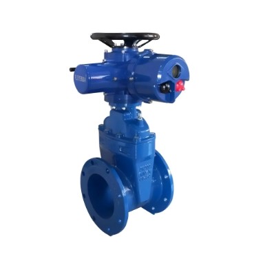
Elektrikli Sürgülü Vana
Multi-turn electric gate valves designed for pipeline isolation in water treatment, power generation and industrial utility systems.
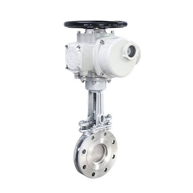
Elektrikli Bıçaklı Sürgülü Vana
Motorized knife gate valve solutions for suitable slurry, wastewater and solids-handling applications.
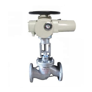
Elektrikle Çalışan Küresel Vana
Electric globe valves for flow adjustment, pressure control and industrial process regulation.
Motor Operated Valve Control Modes
Open-Close Control
On/off motor operated valves move between fully open and fully closed positions. They are primarily used for pipeline isolation, tank filling, draining, equipment switching, and automated shutdown operations.
Positioning Control
Positioning control allows the actuator to move the valve to selected intermediate positions. It is useful when a process requires several predetermined flow settings rather than continuous adjustment.
Modülasyonlu Kontrol
Modulating electric actuators continuously adjust valve position according to a control signal. Common signal options include 4–20 mA and 0–10 V, depending on the actuator configuration.
This control mode is suitable for compatible process applications requiring flow adjustment, dosing, pressure control, or temperature regulation. The actuator must be rated for the expected operating frequency and duty cycle.
Emergency and Fail-Safe Operation
A standard motor operated valve normally remains in its last position when electrical power is lost. It does not automatically move to a fail-open or fail-closed position unless the actuator assembly includes an appropriate backup energy or fail-safe mechanism.
Where emergency movement is required, the system may use a battery, capacitor, uninterruptible power supply, emergency generator, or another engineered stored-energy solution.
Industrial Applications of Motor Operated Valves
Motor operated valves are used wherever automated flow control, remote operation, or reliable pipeline isolation is required. The valve body, sealing materials, actuator, and protection rating must be selected according to the operating environment.
Water and Wastewater Treatment
MOVs are used in water intake systems, filtration units, pumping stations, reservoirs, chemical dosing lines, and distribution networks. Electric operation is particularly useful for remotely located equipment where instrument-air infrastructure is not readily available.
Petrol ve Doğal Gaz İşleme
Motor operated valves support pipeline isolation, tank transfer, process utilities, and automated equipment operation. Hazardous-area installations require appropriate explosion-proof certification and electrical protection for the specific site classification.
Kimyasal İşleme
Electric actuated valves are used for chemical transfer, process isolation, dosing, and fluid routing. Valve body materials and sealing components must be compatible with the medium, concentration, pressure, and temperature.
Elektrik Üretimi
Power plants use MOVs in cooling-water systems, condensate lines, auxiliary pipelines, boiler-related services, and other plant utilities. Selection should account for differential pressure, operating loads, temperature, and duty requirements.
HVAC and Industrial Manufacturing
Motorized valves control chilled water, hot water, ventilation systems, compressed air, cooling circuits, and automated production equipment.
Advantages and Limitations of Motor Operated Valves
Electric motor operated valves provide several benefits for industrial automation, but their suitability depends on process requirements, available power, operating frequency, and maintenance conditions.
Key Advantages
- Remote operation: Supports control from centralized automation systems.
- No instrument-air requirement: Operates without a dedicated compressed-air supply.
- High output torque: Gear-driven actuators can operate demanding industrial valves.
- Position feedback: Supports valve status monitoring and automation.
- Flexible control: Selected models support on/off, positioning, and modulating operation.
- System integration: Can communicate with PLC, DCS, and SCADA systems.
Important Limitations
- Power dependence: Standard actuators require electrical power to move the valve.
- Duty-cycle limits: Excessive operation can cause motor overheating.
- Operating speed: Some electric actuators are slower than pneumatic alternatives.
- Environmental requirements: Protection must match site conditions.
- Commissioning: Incorrect torque and limit settings may affect operation.
- Maintenance: Mechanical transmission and electrical components require periodic inspection.
How to Select the Right Motor Operated Valve
Selecting a suitable motor operated valve requires more than matching the nominal pipe diameter. Engineers must evaluate the valve function, process conditions, actuator output, electrical configuration, and required operating behavior.
1. Identify the Valve Type and Operating Movement
Determine whether the application requires a ball valve, butterfly valve, gate valve, globe valve, or knife gate valve. Confirm whether the valve needs quarter-turn, multi-turn, or linear movement.
2. Confirm the Process Medium and Operating Conditions
Provide the fluid type, concentration, operating temperature, working pressure, differential pressure, flow requirements, and any solid particles present in the medium. These conditions determine the suitable valve body, seat, sealing material, and construction.
3. Calculate the Required Torque or Thrust
The electric actuator must provide sufficient output to overcome the valve’s mechanical resistance under the specified operating conditions.
For rotary valves, consider breakaway torque, running torque, seating torque, unseating torque, and maximum differential pressure. For linear valves, evaluate required thrust and stroke length. The final actuator size should include an appropriate engineering allowance based on the valve manufacturer’s data.
4. Define the Operating Duty and Speed
Specify whether the valve operates occasionally, frequently, or continuously. Provide the expected starts per hour, operating time, required opening and closing speed, and modulation frequency.
5. Select the Electrical Power Supply
Confirm the available supply voltage, AC or DC configuration, phase, frequency, and permitted voltage variation. Common industrial actuator options include 24 VDC, 110 VAC, 220 VAC, and other configurations depending on the selected model.
6. Specify the Control Signal and Feedback
Determine whether the valve requires simple open/close commands or proportional positioning. For modulating service, specify the input signal, such as 4–20 mA or 0–10 V, together with the required position feedback and PLC or DCS interface.
7. Evaluate Environmental and Hazardous-Area Requirements
Consider ambient temperature, humidity, dust, water ingress, corrosion, vibration, and potential exposure to hazardous gases. Outdoor or hazardous-area installations may require appropriate IP protection or certified explosion-proof actuator configurations.
8. Confirm Mounting and Connection Compatibility
Verify the valve connection standard, actuator mounting interface, output drive, stem arrangement, flange dimensions, and available installation space. ISO 5211 is commonly used for mounting compatible quarter-turn actuators.
9. Define the Required Failure Behavior
Determine whether the valve should remain in its last position or move to a specified position during power loss. A fail-open or fail-closed requirement must be addressed through the complete actuator and power-system design.
10. Verify the Complete Valve Assembly
Final verification should include valve travel, operating torque or thrust, operating time, position feedback, electrical controls, mechanical mounting, and performance under representative process conditions.
Motor Operated Valve Selection: Technical Parameters to Confirm
Before ordering an electric motor operated valve, engineers and purchasing teams should prepare a complete technical specification. Providing these parameters reduces selection errors and helps manufacturers recommend a suitable valve-actuator assembly.
| Selection Parameter | Information Required | Neden Önemli? |
|---|---|---|
| Vana Boyutu | DN / NPS / nominal pipe diameter. | Determines valve dimensions and flow capacity. |
| Basınç Değeri | PN, Class, or maximum working pressure. | Ensures pressure suitability. |
| Orta | Water, oil, gas, steam, chemicals, slurry, etc. | Determines body and sealing material compatibility. |
| Sıcaklık | Minimum, normal, and maximum operating temperature. | Affects material and seat selection. |
| Valve Material | Cast iron, carbon steel, stainless steel, and other options. | Determines mechanical and chemical compatibility. |
| Bağlantı | Flanged, threaded, wafer, welded, or sanitary. | Ensures pipeline compatibility. |
| Güç Kaynağı | AC/DC voltage, phase, and frequency. | Ensures electrical compatibility. |
| Control Mode | On/off, positioning, or modulating. | Matches actuator functionality to process demand. |
| Protection | IP rating and hazardous-area classification. | Ensures suitability for installation conditions. |
| Actuator Output | Torque, thrust, speed, and duty cycle. | Ensures reliable mechanical operation. |
What Information Should You Send to a Motor Operated Valve Supplier?
When requesting a quotation, providing complete operating information allows the manufacturer to evaluate the valve body, electric actuator, and control configuration together.
If some technical parameters are not available, provide the pipeline drawing, equipment information, or existing valve model. The manufacturer can then review the available information and identify the remaining selection requirements.
How to Evaluate Motor Operated Valve Manufacturers and Suppliers
Choosing a motor operated valve supplier involves more than comparing unit prices. The manufacturer should be able to match the valve body and electric actuator to the actual process conditions and provide appropriate technical documentation.
- Product range: Confirm whether the supplier offers ball, butterfly, gate, globe, and other motorized valve configurations.
- Engineering capability: Check whether the manufacturer can review torque, pressure, temperature, material, and actuator requirements.
- Actuator options: Evaluate available voltage, control modes, protection ratings, and communication interfaces.
- Quality and testing: Review relevant design standards, pressure testing, inspection procedures, and product documentation.
- Project support: Confirm technical communication, customization capability, spare parts availability, and after-sales support.
For industrial projects, the complete valve-actuator assembly should be evaluated as one operating unit. A suitable electric actuator cannot compensate for an incorrectly selected valve body, sealing material, or process configuration.
Inspection and Maintenance of Motor Operated Valves
Proper maintenance helps maintain operating reliability and reduces unexpected downtime. Inspection should cover both the valve’s mechanical components and the electric actuator’s control system.
Mechanical Inspection
- Inspect the valve body, flange connections, seals, and external corrosion.
- Check the valve stem, shaft, coupling, gearbox, and mounting bolts.
- Verify lubrication and inspect for unusual noise or mechanical vibration.
- Confirm that the valve travels smoothly through its operating range.
Electrical and Control Inspection
- Inspect electrical terminals, cable entries, enclosure seals, and grounding.
- Verify limit switch settings and torque protection according to manufacturer procedures.
- Test local and remote operating commands and position feedback.
- Check alarms, interlocks, communication signals, and backup power functions where applicable.
Functional testing should verify the complete operating sequence under appropriate test conditions. Critical MOV installations may also require periodic diagnostic testing based on plant maintenance procedures.
Frequently Asked Questions About Motor Operated Valves
What does MOV stand for in industrial valves?
MOV stands for Motor Operated Valve. It refers to an industrial valve assembly operated by an electric motor-driven actuator for automated isolation, switching, or flow control.
What is the working principle of a motor operated valve?
An electric motor drives a reduction gearbox, which transfers torque or thrust to the valve stem or shaft. Position sensors and limit switches monitor movement and help stop the actuator at the configured operating position.
What are the main types of motor operated valves?
Motor operated valves are commonly classified by actuator movement into multi-turn, part-turn, and linear types. They can operate gate, globe, ball, butterfly, plug, knife gate, and other compatible industrial valves.
What is the difference between a motor operated valve and an electric actuated valve?
The terms are often used interchangeably. Motor operated valve generally describes a valve driven by an electric motor, while electric actuated valve is a broader commercial term for a valve equipped with an electric actuator.
Can a ball valve be motor operated?
Yes. Ball valves are commonly automated using quarter-turn electric actuators. Motor operated ball valves are available in 2-way and 3-way configurations, with different body materials, connection types, and control options.
Can motor operated valves regulate flow?
Yes, provided the valve construction and actuator are suitable for modulating service. Options may include position control using 4–20 mA or 0–10 V signals. For more controlled throttling, a suitable V-port ball valve or globe control valve may be considered.
Do motor operated valves automatically close during power failure?
No. A standard motor operated valve generally remains in its last position when power is lost. Automatic fail-open or fail-closed operation requires an appropriate backup power or stored-energy arrangement.
How do I calculate the required torque for a motor operated valve?
Torque selection depends on valve design, differential pressure, medium, seating requirements, and operating conditions. Engineers should evaluate breakaway, running, seating, and unseating torque using the valve manufacturer’s data before matching the actuator.
What factors affect motor operated valve prices?
Price depends on valve type, nominal size, pressure rating, body and seat materials, actuator torque, control functions, voltage, protection rating, explosion-proof requirements, and customization. A complete technical specification is needed for an accurate quotation.
What should I check when choosing a motor operated valve supplier?
Evaluate the manufacturer’s product range, engineering selection capability, actuator options, quality documentation, testing procedures, customization support, and ability to match the complete valve assembly to your operating conditions.
Does a motor operated valve use a solenoid coil?
The main drive of a motor operated valve is an electric motor, not a solenoid coil. Some actuator control circuits may contain electromagnetic components, but this does not make an MOV a solenoid valve.
Choosing the Right Motor Operated Valve for Your Application
Motor operated valves provide electric automation for industrial pipeline isolation, flow routing, and process control. Their performance depends on matching the valve construction, actuator movement, output torque or thrust, and control system to the actual operating conditions.
Multi-turn actuators are commonly used for gate and globe valves, part-turn actuators operate ball and butterfly valves, and linear actuators provide axial movement for compatible control and isolation valves.
Before purchasing a motor operated valve, confirm the medium, pressure, temperature, valve size, connection, electrical supply, operating duty, control signal, and environmental requirements. Correct engineering selection helps improve system reliability and reduce maintenance risks.