


Flanged Electric Ball Valve Selection Guide for Industrial Pipelines
A flanged electric ball valve combines the reliable shutoff performance of a quarter-turn ball valve with the installation strength of bolted flange connections and the convenience of electric automation. It is widely selected for industrial pipelines, water treatment plants, chemical processing systems, oil and gas facilities, and automated equipment. Choosing the right electric flanged ball valve requires evaluating more than nominal pipe size. Flange standards, pressure ratings, valve body materials, seat compatibility, operating torque and actuator control functions all influence the final configuration. This guide explains how to select a suitable flanged electric ball valve for different industrial pipeline requirements.
What to Consider When Selecting a Flanged Electric Ball Valve
Before specifying an electric actuated flanged ball valve, engineers should confirm the following technical requirements:
Flange StandardANSI, DIN, JIS or other project-specific connection requirements.
Basınç DeğeriPN10–PN40 or applicable ANSI pressure classes.
Valve MaterialSS304, SS316, WCB or PTFE/PFA-lined construction.
Elektrikli AktüatörTorque, voltage, control mode and environmental protection.
Recommended Flanged Electric Ball Valve Products
Fleyenda offers different electric flanged ball valve configurations for industrial isolation, automated flow routing and corrosive-media handling. Select the valve construction according to your pipeline requirements.
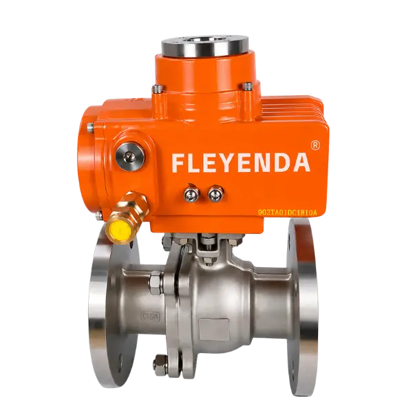
FLE-Q-F Electric 2-Way Flanged Ball Valve
The FLE-Q-F is a general-purpose flanged electric ball valve designed for automated pipeline isolation. Its full-bore construction helps reduce flow restriction when fully open, while the electric quarter-turn actuator supports remote operation and integration with PLC-based control systems.
Typical applications: Water treatment, oil pipelines, industrial equipment, utility systems and automated process isolation.
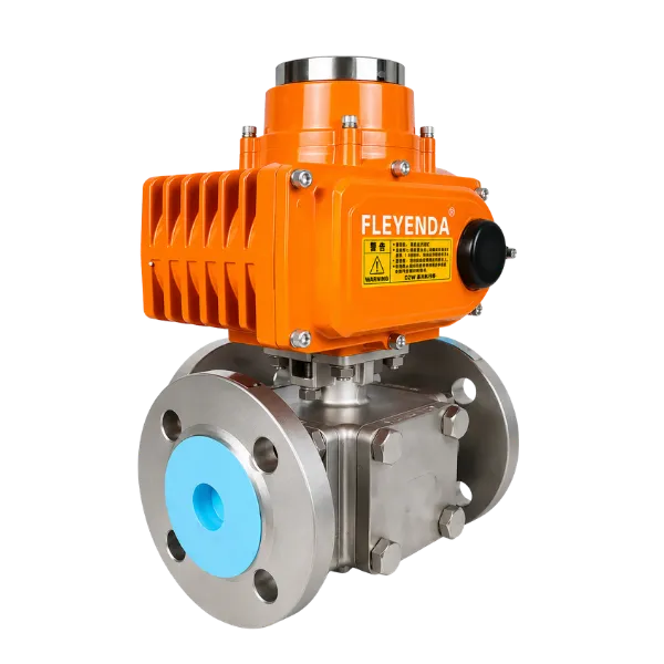
FLE-Q-TF Electric 3-Way Flanged Ball Valve
The FLE-Q-TF is designed for industrial pipelines requiring automated flow diversion, bypass and selected mixing or distribution functions. Available L-port and T-port configurations allow engineers to select different flow paths through three connected pipeline branches.
Typical applications: Pipeline bypass, tank selection, water distribution, equipment switching and industrial process routing.
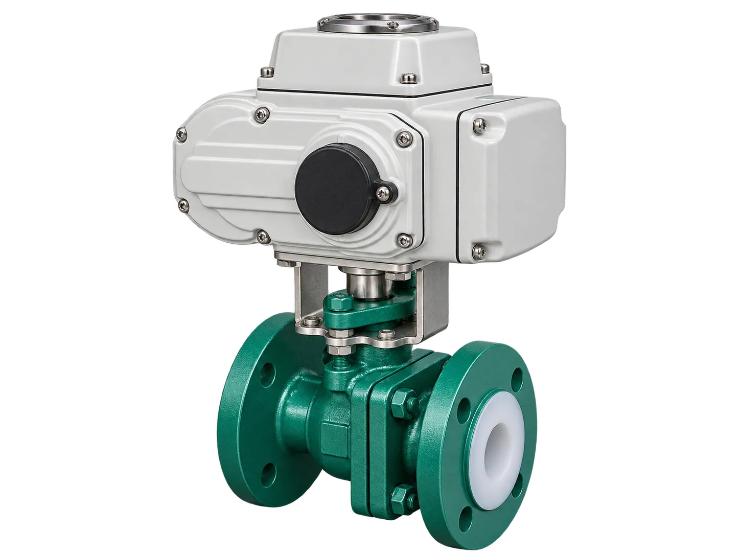
FLE-Q-F PTFE/PFA-Lined Electric Ball Valve
For corrosive process pipelines, the fluoropolymer-lined FLE-Q-F configuration provides a PTFE or PFA-lined wetted flow path. The electric actuator enables remote isolation in compatible chemical transfer, acid and alkali handling, and chemical wastewater applications.
Typical applications: Compatible acid and alkali transfer, chemical dosing, corrosive liquid handling and industrial wastewater systems.
*Temperature and pressure limits depend on valve size, lining, seat materials and process medium. Confirm the final technical configuration before ordering.
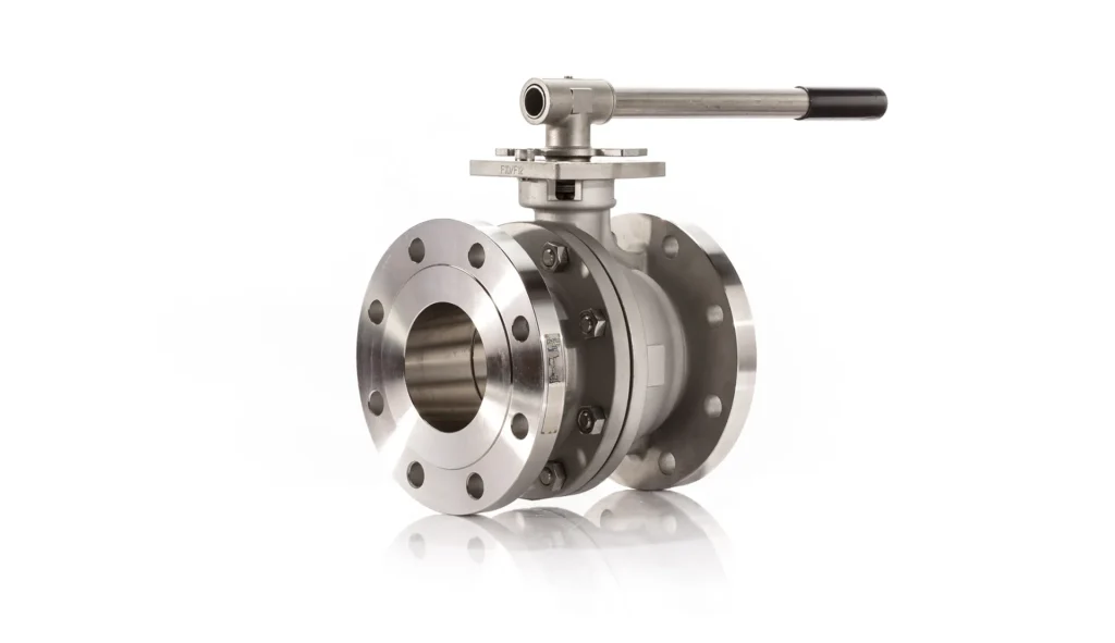
1. What Is a Flanged Electric Ball Valve?
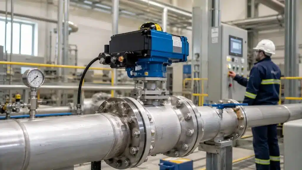
A flanged electric ball valve is an automated ball valve assembly consisting of a valve body with flanged ends and an electric quarter-turn actuator. The flanges connect the valve to the pipeline using bolts and gaskets, while the actuator rotates the internal ball to open or close the flow passage.
When the valve is fully open, the ball port aligns with the pipeline, allowing fluid to pass through. When the actuator rotates the ball approximately 90 degrees, the flow passage becomes blocked and the pipeline is isolated.
The main components include:
- Valve body: Provides the pressure-containing structure and flanged pipeline connections.
- Ball and stem: Control the flow passage through quarter-turn rotation.
- Valve seats: Provide sealing between the ball and valve body.
- Electric actuator: Generates the torque needed to operate the valve.
- Mounting interface: Connects the actuator to the valve, commonly using ISO 5211 configurations.
Compared with manual operation, an electric flanged ball valve allows remote switching, centralized control and automated operating sequences. It is particularly useful in industrial facilities where valves are distributed across large pipeline networks or integrated into automated equipment.
The term flange end electric ball valve generally refers to the same basic assembly: an electric-actuated ball valve with bolted flange connections. Its actual performance depends on the selected valve construction, sealing materials and actuator configuration.
2. Why Choose an Electric Flanged Ball Valve for Industrial Pipelines?
Flanged connections are widely used in industrial piping systems because they provide a bolted mechanical interface between the valve and adjoining pipeline components. When combined with electric actuation, they offer a practical solution for automated isolation in permanent process installations.
Secure Bolted Pipeline Connections
Flanged ends connect to matching pipeline flanges through bolts and compatible gaskets. Correct flange alignment and bolt tightening help create a reliable connection under the specified operating conditions.
Suitable for Larger Pipeline Sizes
Threaded connections are commonly used in smaller-bore piping. Flanged electric ball valves provide a practical connection option for larger industrial pipelines, equipment skids and fixed process systems. Fleyenda’s standard FLE-Q-F series covers DN15–DN300.
Convenient Maintenance and Replacement
Because the valve is connected through bolted flanges, the assembly can be removed during planned maintenance without cutting the pipeline. Adequate installation space should be reserved for bolt removal, actuator access and lifting where necessary.
Integration with Industrial Automation
An electric actuator allows the valve to receive commands from local control panels, PLCs or centralized automation systems. Depending on the selected configuration, functions may include open/close control, position feedback and modulating operation.
Multiple Connection Standards
Industrial projects may specify ANSI, DIN or JIS flange connections. A flanged motorized ball valve can be configured to match the relevant pipeline standard, but the nominal size alone is not sufficient to confirm compatibility. Flange drilling, pressure class, facing and dimensions must also be checked.
3. Two-Way vs. Three-Way Flanged Electric Ball Valves
One of the first decisions when selecting a flanged electric ball valve is whether the pipeline requires simple isolation or automated flow routing.
Two-Way Electric Flanged Ball Valve
A two-way valve has one inlet and one outlet. Its main function is to open or close a single pipeline path. The FLE-Q-F is a typical two-way electric flanged ball valve designed for automated isolation and remote shutoff.
Typical applications include pump isolation, water distribution, chemical transfer, oil pipelines and industrial equipment connections.
Three-Way Electric Flanged Ball Valve
A three-way valve has three pipeline connections. Depending on the internal ball design, it can divert a flow stream between different outlets or connect selected flow paths.
The FLE-Q-TF series provides L-port and T-port configurations. L-port arrangements are commonly used for switching between alternative branches, while T-port designs can support broader distribution or selected mixing arrangements.
| Karşılaştırma | 2-Way | 3-Way |
|---|---|---|
| Pipeline Ports | 2 | 3 |
| Main Function | Open / Close Isolation | Diverting / Distribution / Selected Mixing |
| Ball Design | Straight-through Port | L-Port / T-Port |
| Typical Use | Pipeline Shutoff | Bypass and Flow Routing |
| Seçim Önceliği | Size, Pressure and Torque | Port Arrangement and Flow Logic |
A three-way valve is not simply a replacement for two-way isolation valves. Its port configuration must match the actual piping diagram and operating sequence. For continuous proportional flow regulation, a suitable V-port valve or dedicated control valve may be more appropriate than a standard round-port ball valve.
4. How to Select the Right Flange Standard and Pressure Rating
Flange compatibility is a critical factor when specifying an electric flange ball valve. The connection must match the pipeline’s flange standard, nominal size, pressure class, facing and bolt arrangement.
ANSI Flanged Ball Valves
ANSI flanges are widely used in North American and international industrial projects. ASME B16.5 defines flange dimensions and pressure-temperature ratings for the applicable size and class range.
When ordering an ANSI flanged electric ball valve, confirm the required Class 150 or Class 300 rating, flange facing, drilling and mating-pipe specification.
DIN / EN Flanged Ball Valves
DIN and EN flange specifications are commonly encountered in European-style industrial piping systems. The PN rating identifies the nominal pressure designation, while actual allowable working pressure depends on the applicable material, temperature and standard.
JIS Flanged Ball Valves
JIS flange connections are used in projects following Japanese Industrial Standards. Confirm the specified nominal pressure designation and flange dimensions rather than assuming a JIS connection will match an ANSI or DIN flange.
| Bağlantı Standardı | Common Designation | Important Checks |
|---|---|---|
| ANSI / ASME | Class 150 / 300 | Flange drilling, facing and pressure-temperature rating |
| DIN / EN | PN10 / PN16 / PN25 / PN40 | PN designation, dimensions and mating flange |
| JIS | 10K and other applicable ratings | JIS flange dimensions and project requirements |
PN ratings and ANSI pressure classes should not be treated as directly interchangeable. Before ordering, provide the actual pipeline standard and pressure class to ensure the electric flanged ball valve matches the existing piping.
5. Stainless Steel, Carbon Steel and PTFE-Lined Valve Materials
The valve body, ball, seats and sealing components must be compatible with the process medium. Material selection affects corrosion resistance, pressure capability, temperature limits and expected service life.
SS304 Stainless Steel
SS304 is commonly selected for general industrial water, compatible process liquids and applications where moderate corrosion resistance is sufficient. It offers a practical balance of mechanical properties and corrosion resistance.
SS316 / SS316L Stainless Steel
SS316 and SS316L are often considered for more demanding chemical environments where improved resistance to certain corrosive media is required. Selection should consider chemical concentration, temperature and exposure conditions.
Carbon Steel WCB
WCB carbon steel is commonly used in general industrial pipeline services where mechanical strength, pressure rating and cost are important considerations. It should be evaluated against the actual fluid chemistry and corrosion allowance requirements.
PTFE / PFA-Lined Construction
For compatible corrosive media, PTFE or PFA lining provides a fluoropolymer barrier between the process fluid and metallic pressure-containing body. These constructions are often considered for selected acid, alkali, solvent and chemical wastewater services.
| Malzeme | Main Characteristics | Typical Selection |
|---|---|---|
| SS304 | Genel korozyon direnci | Compatible industrial water and process fluids |
| SS316 / SS316L | Improved resistance to certain corrosive environments | More demanding chemical services |
| WCB | Mechanical strength for industrial pressure applications | Compatible water, oil, gas and utility pipelines |
| PTFE / PFA Lining | Fluoropolymer-lined wetted flow path | Compatible acids, alkalis and corrosive media |
Seat materials also need to be considered. PTFE, reinforced PTFE and other seat configurations have different friction, sealing and temperature characteristics. Always verify the complete wetted assembly rather than selecting a valve based only on its external body material.
6. Electric Actuator Selection: Torque, Voltage and Control
The actuator is responsible for operating the ball valve under the actual pipeline conditions. A properly selected flanged motorized ball valve requires sufficient actuator torque, compatible electrical supply and the correct control configuration.
Operating Torque
Required torque depends on valve size, differential pressure, seat material, fluid characteristics, operating frequency and service conditions. Actuator sizing should be based on the manufacturer’s torque data, with an appropriate engineering margin.
Power Supply Options
Depending on the selected actuator model, common voltage configurations include DC24V, AC24V, AC110V, AC220V and AC380V. The electrical supply should match the available power system and actuator specification.
ON/OFF and Modulating Control
ON/OFF actuators are primarily used for automatic opening and closing. Selected modulating configurations can support intermediate positioning through compatible control signals such as 4–20 mA or 0–10 V.
However, a standard full-port ball valve is primarily designed for shutoff. If the process requires accurate continuous flow regulation, engineers should evaluate valve geometry, Cv/Kv, pressure drop and the installed flow characteristic before specifying a modulating electric actuated flanged ball valve.
IP Protection and Explosion-Proof Options
Actuator protection should match the installation environment. Selected Fleyenda configurations offer IP67 protection, optional IP68 and explosion-proof Ex d II BT4 / CT4 / CT6 Gb options. The actual actuator certificate and protection grade must be confirmed for the selected model.
Power Failure and Manual Operation
A standard electric actuator does not necessarily move the valve to a safe position when power is lost. If the process requires fail-open or fail-closed operation, specify a compatible fail-safe arrangement and verify its operating principle. Manual override may also be considered for selected actuator configurations.
7. Industrial Applications of Flanged Electric Ball Valves
Electric flanged ball valves are used in a wide range of industrial systems where reliable pipeline connections and automated isolation are required.
Water and Wastewater Treatment
Electric flanged ball valves can automate isolation around pumps, filtration equipment, dosing systems and water distribution pipelines. Valve material and actuator protection should be selected according to water chemistry, dosing chemicals and outdoor installation conditions.
Kimyasal İşleme
Chemical plants use automated valves to isolate compatible process liquids and utility pipelines. Stainless steel or PTFE/PFA-lined constructions can be selected according to the fluid concentration, operating temperature and corrosion requirements.
Oil and Gas Pipelines
Electric actuated flanged ball valves can be used for automated isolation in compatible oil, gas and utility services. Pressure class, leakage requirements, fire-safe design and hazardous-area actuator protection must be evaluated against project specifications.
HVAC and Industrial Utilities
Flanged electric ball valves are suitable for selected water and utility pipelines in industrial heating, cooling and building equipment systems. Their electric actuation allows integration with centralized control systems.
Metallurgy and Heavy Industry
In metallurgical facilities, electric flanged ball valves can support automated isolation in compatible cooling-water circuits, auxiliary process pipelines and equipment utility systems. High operating frequency, differential pressure and environmental conditions should be considered during selection.
OEM Equipment and Process Skids
Equipment manufacturers can integrate electric flanged ball valves into pump skids, industrial machinery, dosing packages and automated process modules. Installation dimensions, actuator torque, wiring access and maintenance space should be confirmed before equipment design is finalized.
8. How to Select the Right Flanged Electric Ball Valve
Choosing the right valve requires a complete review of process conditions, pipeline specifications and automation requirements. The following selection steps can help avoid common specification mistakes.
Step 1: Identify the Process Medium
Provide the fluid name, chemical composition, concentration, viscosity and any special characteristics. This information determines the suitable valve body, ball, seat and seal materials.
Step 2: Confirm the Pipeline Size
Specify the nominal diameter in DN or inches. The valve bore and flow capacity should be reviewed against the required flow rate and system pressure drop.
Step 3: Confirm the Flange Standard
Identify whether the pipeline requires ANSI, DIN, JIS or another flange standard. Include the pressure class, flange facing and relevant connection dimensions.
Step 4: Define Pressure and Temperature
Provide normal operating pressure, maximum design pressure, operating temperature and any pressure surges or temperature fluctuations. Confirm the allowable pressure-temperature envelope of the selected valve configuration.
Step 5: Select the Valve Flow Function
Determine whether the system requires two-way isolation or three-way flow routing. For three-way valves, provide the required L-port or T-port connection logic.
Step 6: Match the Electric Actuator
Specify operating torque, voltage, opening and closing time, ON/OFF or modulating control, feedback and manual override requirements.
Step 7: Confirm Environmental and Safety Requirements
Identify indoor or outdoor installation, IP protection, ambient temperature, hazardous-area classification and any required explosion-proof or fire-safe options.
For accurate technical selection, provide a valve datasheet or pipeline specification. This allows the manufacturer to evaluate the complete valve and actuator assembly rather than recommending a product based only on DN size.
9. Installation and Maintenance of Electric Flanged Ball Valves
Correct installation and routine inspection help maintain the sealing performance and operating reliability of a flanged electric ball valve.
Check Flange Alignment
Ensure the mating pipe flanges are properly aligned before tightening the bolts. Forced alignment can introduce mechanical stress into the valve body and affect long-term sealing performance.
Use Compatible Gaskets and Bolting
Select gasket materials and bolt specifications suitable for the flange standard, operating medium, pressure and temperature. Tighten bolts using the appropriate sequence and torque requirements.
Check Valve Flow Direction
Confirm the valve’s intended flow direction and port arrangement, especially for three-way configurations. The actuator position should match the required pipeline switching logic.
Inspect Electrical Connections
Check power supply, cable entries, grounding and control wiring before commissioning. Verify open and closed position limits, feedback signals and actuator rotation direction.
Perform Operating and Leakage Tests
Before putting the pipeline into service, verify actuator operation, valve travel and the required leakage performance under the specified test procedure. Follow the applicable product testing standard and project acceptance criteria.
Schedule Routine Maintenance
Inspect the actuator enclosure, flange joints, stem seals, valve seats and electrical connections according to the service environment and operating frequency. Unusual operating torque, leakage or slow actuator response should be investigated before it causes equipment downtime.
Frequently Asked Questions About Flanged Electric Ball Valves
What is a flanged electric ball valve used for?
A flanged electric ball valve is primarily used for automated pipeline isolation and remote flow switching. It is widely applied in water treatment, chemical processing, oil and gas, industrial utilities and equipment automation systems.
What is the difference between an electric flanged ball valve and a threaded electric ball valve?
An electric flanged ball valve uses bolted flange connections and is commonly selected for fixed industrial pipelines and larger pipe sizes. A threaded electric ball valve uses NPT, BSP or other compatible threaded connections and is often used in smaller-bore pipelines and compact equipment.
What does flange end electric ball valve mean?
A flange end electric ball valve is a ball valve equipped with an electric actuator and flanged end connections. The flange interfaces connect to matching pipeline flanges through bolts and gaskets. The applicable flange standard and pressure rating must be confirmed before ordering.
Which flange standards are available for Fleyenda electric ball valves?
The FLE-Q-F and FLE-Q-TF product configurations list ANSI, DIN and JIS flanged connection options. Actual flange dimensions, pressure class and facing should be confirmed against the selected product datasheet.
What size range is available for FLE-Q-F?
The standard FLE-Q-F Electric 2-Way Flanged Ball Valve covers DN15–DN300 (½″–12″), with PN16–PN40 and ANSI Class 150–300 configurations listed. Confirm the size-specific pressure rating before ordering.
Can a flanged motorized ball valve be controlled by a PLC?
Yes. Depending on the selected electric actuator, the valve can support ON/OFF commands, position feedback and selected modulating control signals. Voltage, wiring, feedback and control functions should be matched to the PLC or DCS system.
What is the difference between a standard and PTFE-lined electric flanged ball valve?
A standard valve exposes its specified metallic wetted surfaces to the process medium. A PTFE/PFA-lined electric flanged ball valve uses a fluoropolymer-lined flow path for compatible corrosive media. The lining, seat and seals must be selected according to chemical concentration and operating temperature.
Can an electric actuated flanged ball valve be used for continuous flow regulation?
Selected electric actuators support modulating control, but a standard full-port ball valve is primarily designed for isolation. For more predictable continuous flow regulation, consider a V-port ball valve or dedicated control valve and confirm the required Cv/Kv and pressure drop.
What information is required to order a flanged electric ball valve?
Provide valve size, flange standard, pressure rating, operating temperature, process medium, body and seat materials, actuator voltage, control mode, required torque, IP rating and any explosion-proof or fire-safe requirements. A pipeline drawing or equipment datasheet is useful for technical confirmation.
Looking for a Flanged Electric Ball Valve for Your Industrial Pipeline?
Fleyenda supplies electric flanged ball valves for industrial pipeline isolation, flow routing and compatible process applications. From standard two-way full-bore designs to three-way flow-routing valves and PTFE/PFA-lined configurations, different valve constructions can be selected according to your project requirements.
Send us your pipeline size, flange standard, pressure, temperature, process medium and actuator requirements. Our team can help evaluate a suitable valve configuration for your application.
Email: inquiry@fleyendaflow.com