


Pneumatic 3 Way Valve
A pneumatic 3 way valve is used to direct fluid between three pipeline connections through an air-operated valve mechanism. In industrial process systems, a pneumatic three-way ball valve can switch flow between two outlets, select between different supply lines, or connect multiple process paths without manual operation.
Unlike a conventional two-way valve that mainly opens or closes a single flow passage, a three-way valve changes the connection between different pipelines. This makes it useful for automated liquid transfer, pump bypass systems, tank switching, chemical processing, water treatment, and other operations requiring automatic flow routing.
Not every pneumatic 3 way valve provides the same flow arrangement. The internal ball may have an L-port or T-port passage, and the actuator may operate through 90-degree, 180-degree, or multiple defined positions depending on the required flow paths.
Proper selection requires evaluating the internal port configuration, actuator torque, air supply pressure, fail-safe behavior, body materials, connections, and actual process conditions.
Start with the required flow paths. Define which physical ports must communicate at every operating position before selecting the valve body and pneumatic actuator.
What Is a Pneumatic 3 Way Valve?
A pneumatic 3 way valve is an air-operated valve assembly designed to control fluid connections between three ports. In industrial piping, it commonly refers to a pneumatic three-way ball valve with a three-port body, an internally drilled ball, and a rotary pneumatic actuator.
Instead of turning a manual handle, compressed air powers the actuator. The actuator generates torque and rotates the valve stem, changing the orientation of the internal ball and the resulting flow path.
Depending on its internal arrangement, a pneumatic three-way valve may direct one inlet toward two alternative outlets, select between two supply lines, or connect several flow passages for selected distribution or mixing duties.
3-Way Process Valve vs 3/2-Way Pneumatic Directional Valve
The term pneumatic 3 way valve can also refer to a directional control valve used within a compressed-air control circuit.
A 3/2-way directional valve normally has three air ports and two positions. It is commonly used to supply or exhaust compressed air for pneumatic equipment.
A pneumatic three-way ball valve, by comparison, controls the process medium flowing through an industrial pipeline, such as water, oil, gas, or compatible chemical liquids.
For industrial fluid-handling projects, specifying pneumatic three-way ball valve helps distinguish the process valve from a pneumatic control accessory.
How Does a Pneumatic 3 Way Valve Work?
A pneumatic three-way ball valve commonly uses a rotary pneumatic actuator, often with a rack-and-pinion mechanism. Compressed air moves internal pistons or another mechanical drive mechanism, generating torque at the actuator output shaft.
The actuator shaft rotates the valve stem. As the ball changes position, its internal L-shaped or T-shaped passage connects different ports in the valve body.
An electrically operated pilot solenoid valve may receive commands from a PLC or DCS and direct instrument air to the actuator. Optional limit switches provide feedback when the actuator reaches its configured positions.
Typical Operating Sequence
- The PLC or local controller sends a valve-switching command.
- The pilot solenoid directs air into the actuator.
- The actuator develops torque and turns the valve stem.
- The internal ball moves to the specified flow-routing position.
- Position feedback confirms the completed movement where available.
- The control system proceeds after required interlocks are satisfied.
A conventional two-position quarter-turn actuator should not automatically be assumed suitable for every three-way valve flow diagram. Certain T-port configurations require intermediate positioning, a different travel angle, or specialized multi-position actuation.
L-Port vs T-Port Pneumatic 3 Way Valve
The internal port arrangement determines how a three-way valve connects pipelines. L-port and T-port designs offer different flow-routing functions and should be selected according to the complete operating sequence.
L-Port Pneumatic 3 Way Valve
An L-port valve has an L-shaped passage through the ball. It is primarily used to connect one common port with one of two alternative ports.
This configuration is frequently suitable for diverting one inlet toward either of two outlets or selecting between two sources feeding a common process line.
In automated production systems, L-port valves are commonly used for tank changeover, supply-line selection, and fluid transfer between alternative destinations.
T-Port Pneumatic 3 Way Valve
A T-port valve has a T-shaped passage that can support additional flow combinations. Depending on the specific ball drilling and actuator positions, it may connect two ports or allow communication among all three.
This configuration can be useful for selected bypass, distribution, recirculation, and combining applications.
Not every T-port valve provides identical routing positions or complete branch isolation. The manufacturer-specific flow diagram must be checked.
| Factor | L-Port | T-Port |
|---|---|---|
| Internal Passage | L-shaped | T-shaped |
| Primary Function | Diversion or source selection | Distribution, bypass, or selected mixing |
| Three-Port Communication | Not normally available | Possible in selected configurations |
| Actuator Travel | Depends on required positions | May require 90°, 180°, or multi-position travel |
| Typical Application | Tank or pipeline changeover | Bypass and process distribution |
| Selection Priority | Common port and alternative routes | All connected paths at each position |
Before ordering an L-port or T-port pneumatic ball valve, request a flow-position drawing identifying every physical port, required actuator angle, and expected flow path.
Double-Acting and Spring-Return Pneumatic 3 Way Valves
The pneumatic actuator determines how the valve moves between operating positions and what happens when the instrument-air supply is interrupted.
Double-Acting Pneumatic Actuator
A double-acting actuator uses compressed air for movement in both directions. It is commonly selected for general industrial switching where compressed air is consistently available.
Loss of air supply does not automatically guarantee a particular failure position. Applications requiring fail-in-place operation must use a suitable, verified pneumatic circuit.
Spring-Return Pneumatic Actuator
A spring-return actuator uses compressed air to move in one direction and stored spring energy to return toward a predefined position.
For three-way valves, the failure position must be described by the resulting port connections. A simple fail-open or fail-close description may not adequately describe a flow-diverting valve.
For example, the application may require the common inlet to connect to a return line, prevent chemical feeding, or maintain cooling-water flow when air pressure is lost.
Air Supply and Accessories
Pneumatic actuator sizing must be based on the minimum guaranteed air pressure and the valve operating torque under actual process conditions.
Available control accessories can include pilot solenoid valves, air filter regulators, limit switch boxes, position indicators, and positioners for suitable regulating assemblies.
In three-way valve applications, define the required position during loss of air, loss of electrical command, and emergency shutdown separately. These events do not necessarily produce the same result.
Fleyenda Pneumatic 3 Way Valve Solutions
Explore pneumatic three-way ball valve configurations for high-pressure industrial piping, chemical handling, water treatment, and sanitary process applications. Each product below links directly to its individual Fleyenda product detail page.
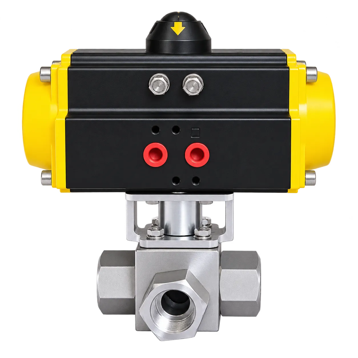
The FAT-Q-TG is a high-pressure pneumatic three-way ball valve intended for automated switching between industrial process flow paths.
Its stainless steel construction and pneumatic actuator make it suitable for selected applications where operating pressure, sealing performance, and actuator torque must be evaluated carefully.
The final valve and actuator configuration should be confirmed using the required flow diagram, pipeline pressure, connection standard, and medium compatibility.
Applications: high-pressure process piping, oil and gas processing, chemical handling, and industrial flow-routing systems.
| Model | FAT-Q-TG | Gamme de tailles | DN8–DN100 / 1/4″–4″ |
| Pressure | Up to 1000 PSI, subject to configuration | Temperature | de -20 °C à +180 °C |
| Matériau de la carrosserie | Stainless Steel / CF8M | Operation | Pneumatic |
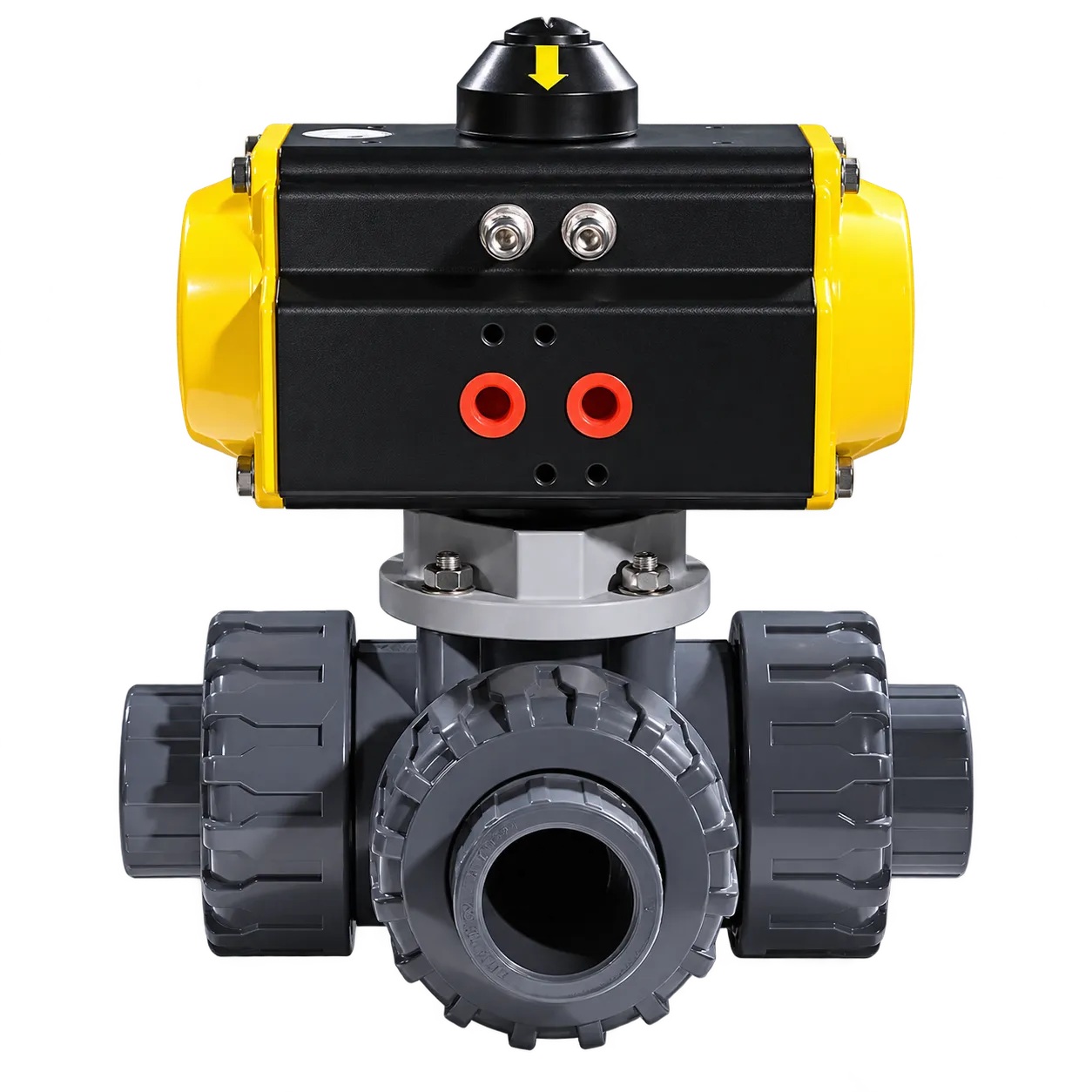
The FAT-Q-PD is a pneumatic three-way ball valve featuring thermoplastic body construction and double-union connections.
Its material options make it suitable for selected water treatment and chemical systems where compatibility with the process medium is an important consideration.
Double-union connections can simplify valve removal for inspection and maintenance when sufficient installation clearance is available.
The correct body and seat materials should be selected based on chemical concentration, operating temperature, and process pressure.
Applications: water treatment, chemical dosing, compatible acids and alkalis, and automated fluid distribution.
| Model | FAT-Q-PD | Gamme de tailles | DN15–DN100 |
| Pressure | PN10–PN16, subject to material and temperature | Body Options | UPVC / CPVC / PVDF |
| Temperature | Depends on thermoplastic material | Connection | Double Union |
| Actionneur | Double Acting / Spring Return | Air Supply | 4–7 bar listed configuration |
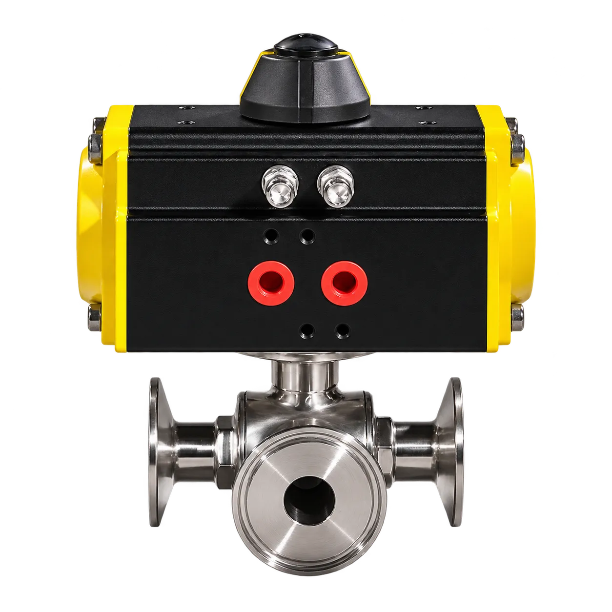
The FAT-Q-3S is a stainless steel pneumatic three-way ball valve with sanitary Tri-Clamp connections for selected hygienic fluid-processing duties.
Stainless steel body options and pneumatic actuation make this series suitable for automated switching in compatible food, beverage, dairy, and other sanitary processing systems.
The complete valve assembly should be evaluated for cleaning requirements, surface finish, sealing materials, and the intended hygienic process.
Applications: food and beverage processing, dairy transfer, sanitary production lines, and compatible pharmaceutical fluid systems.
| Model | FAT-Q-3S | Gamme de tailles | DN15–DN100 / 1/2″–4″ |
| Pressure | 0–10 bar | Temperature | de -20 °C à +180 °C |
| Matériau de la carrosserie | SS304 / SS316L | Connection | Tri-Clamp |
| Actionneur | Double Acting / Spring Return | Port Options | L-Port / T-Port |
Where Are Pneumatic 3 Way Valves Used?
Pneumatic three-way valves are used where fluid must be redirected automatically or where equipment requires alternative pipeline connections. Their main applications include water treatment, pump systems, oil and gas processing, chemical transfer, and sanitary production.
Water Treatment Systems
Pneumatic three-way ball valves can switch between treatment lines, route process water to alternative equipment, or automate selected chemical dosing and flushing circuits.
Material compatibility, valve size, pressure loss, and the required port connections should be verified before installation.
Pump Systems and Pump Skids
A pneumatic three-way valve can change routing between normal and bypass lines or select different destinations for pumped fluids.
The control sequence must verify the intended port arrangement before pump startup or line switching. Valve speed should be evaluated to reduce the risk of hydraulic pressure transients.
Oil and Gas Processing
Selected pneumatic three-way ball valves may be used for process routing, sampling, fluid distribution, and automated switching duties.
Pressure rating, materials, leakage requirements, pneumatic actuator sizing, and hazardous-area requirements are important selection criteria.
Chemical Processing
Three-way valves can direct compatible chemical streams between process equipment, storage vessels, and transfer lines.
If incompatible chemicals must remain separated, the required port isolation and sealing arrangement must be checked carefully.
Food and Beverage Processing
Sanitary three-way pneumatic ball valves can be considered for selected production lines requiring automatic transfer or flow diversion.
Cleanability, surface finish, compatible seals, drainability, and applicable hygienic design requirements should be verified for the actual process.
How to Select the Right Pneumatic 3 Way Valve
Valve selection should begin with the required flow-routing function rather than nominal pipe size alone.
First, identify which ports must communicate at each operating position. Then determine the valve size, operating pressure, differential pressure, process temperature, fluid compatibility, and installation connection.
The pneumatic actuator should be selected after the valve torque requirements and available instrument-air pressure are established.
| Selection Item | What to Specify | Why It Matters |
|---|---|---|
| Flow Function | Divert, select, distribute, or mix | Determines port arrangement |
| Port Pattern | L-Port or T-Port with flow diagram | Prevents incorrect routing |
| Valve Size | DN / NPS | Determines connection dimensions |
| Pressure | Working and differential pressure | Affects pressure rating and torque |
| Temperature | Minimum and maximum process temperature | Affects valve and seat materials |
| Medium | Water, oil, gas, or specific chemical | Determines material compatibility |
| Connection | Threaded, flanged, union, or sanitary | Determines installation suitability |
| Air Supply | Minimum available pressure | Determines actuator output torque |
| Actionneur | Double acting or spring return | Determines operating and failure behavior |
| Travel Angle | 90°, 180°, or selected intermediate positions | Must match required flow paths |
| Accessoires de commande | Pilot solenoid, limit switch, positioner, F.R.L. | Enables automation and feedback |
How to Choose the Correct Valve Size
Valve size is usually related to the pipeline connection and acceptable pressure loss. For a three-way valve, capacity should be checked for every flow route used in the process.
If the valve handles significantly different flow rates between operating positions, the required Cv or Kv should be evaluated for each relevant flow path.
For proportional flow control, both the valve flow characteristics and the actuator positioning capability must be suitable for the application.
How to Select Pneumatic Actuator Torque
Pneumatic actuator sizing depends on the valve’s required torque under actual pressure, temperature, and medium conditions.
The selected actuator must provide sufficient output torque at the minimum available air pressure, with an appropriate engineering safety margin.
Pneumatic 3 Way Valve Installation and Troubleshooting
Installation begins by identifying all three valve ports and comparing them with the approved flow-position diagram.
The valve should be installed with the correct routing orientation, and pipeline loads should be supported independently to avoid excessive stress on the valve body.
Before applying instrument air, verify the actuator supply pressure, rotation direction, pneumatic connections, and required failure behavior.
During commissioning, confirm the connected flow paths at every commanded position and verify any limit switch or position feedback signals.
Common Problems
| Problème | Cause possible | What to Check |
|---|---|---|
| Wrong outlet receives flow | Incorrect port arrangement or actuator indexing | Flow diagram and valve orientation |
| Actuator does not complete travel | Insufficient air pressure or torque | Air supply and actuator sizing |
| Unexpected cross-flow | Incorrect position or internal leakage | Port arrangement and sealing condition |
| Slow operation | Restricted supply or exhaust | Tubing, regulator, and pilot circuit |
| No feedback | Limit switch or wiring issue | Switch adjustment and controller inputs |
| Incorrect fail position | Wrong actuator or pneumatic configuration | Spring arrangement and failure sequence |
Request a Pneumatic 3 Way Valve Configuration & Quote
Fleyenda supports industrial buyers, equipment manufacturers, and engineering projects with pneumatic three-way valve configurations for flow diversion, high-pressure switching, chemical handling, and automated processing systems.
To identify the right valve and actuator combination, provide the application details below. A P&ID, piping sketch, or three-way flow-position diagram is especially helpful.
DN / NPS, flanged, threaded, union, or sanitary
L-Port / T-Port and each operating position
Medium, pressure, temperature, and differential pressure
Stainless steel or compatible thermoplastic
Minimum air pressure and required failure position
Pilot solenoid, feedback, positioner, and PLC requirements
Send your process requirements or technical drawings to Fleyenda for a suitable pneumatic three-way valve configuration and quotation.
Foire aux questions
What is a pneumatic 3 way valve?
A pneumatic 3 way valve is an air-operated valve with three fluid connections. Industrial three-way ball valves use an internal L-port or T-port passage to route process fluid between different pipelines.
What is the difference between an L-port and T-port valve?
An L-port valve primarily connects a common port to one of two alternatives. A T-port valve may provide additional mixing, bypass, or distribution arrangements depending on its specific internal design.
Can a pneumatic 3 way valve divert water between two tanks?
Yes. A correctly configured L-port three-way ball valve can direct a common inlet toward either of two outlet lines.
What air pressure is required?
The required pressure depends on actuator size and valve torque. Always verify the minimum available air pressure against the selected actuator’s torque characteristics.
What is the difference between double acting and spring return?
Double-acting actuators use compressed air in both directions. Spring-return actuators use stored spring force to reach a predefined position when the relevant air supply is removed.
Can a pneumatic 3 way valve be controlled by a PLC?
Yes. A PLC can command the actuator through a suitable pilot circuit and receive position feedback from a limit switch box or position transmitter.
Can a T-port pneumatic valve be used for mixing?
Selected T-port designs allow compatible streams to be combined. Precise proportional mixing requires suitable valve flow characteristics and actuator positioning capability.
Are pneumatic plastic 3-way valves suitable for chemicals?
They may be suitable for specific chemical applications if the valve body, seats, and seals are compatible with the chemical concentration, pressure, and temperature.
What should be included in an RFQ?
Include the port flow diagram, size, connection, medium, pressure, temperature, actuator type, instrument-air pressure, failure position, and required control accessories.
Conclusion
A pneumatic 3 way valve provides an efficient way to automate fluid routing between three pipeline connections. Its performance depends on the internal port arrangement, valve construction, actuator configuration, and required process sequence.
L-port valves are generally suitable for diversion and source selection, while T-port valves provide additional possibilities for mixing, bypass, and distribution. The actual flow paths must always be verified against the specific manufacturer’s drawing.
For water treatment, pump systems, oil and gas, chemical processing, and sanitary applications, selecting the complete pneumatic valve-and-actuator assembly helps improve operating reliability and simplify system integration.