


How to Control a Motorized Ball Valve?
A motorized ball valve can be controlled by a local switch, electrical relay, PLC, DCS or automatic control system. Depending on the actuator configuration, the valve can operate in fully open and fully closed positions or move proportionally to an intermediate position for flow regulation.
However, controlling a motorized ball valve involves more than connecting power and pressing an open button. The actuator must receive the correct electrical supply and command signal, the valve must stop at its intended position, and the control system should confirm that movement has been completed.
Industrial applications introduce additional requirements. A valve installed on a pump discharge line may need to open before the pump starts. A valve used for flow regulation must follow a control signal accurately. A valve in a hazardous process may require a defined response during power failure or emergency shutdown.
This guide explains how to control a motorized ball valve using on-off commands, electrical wiring, PLC logic, 4–20 mA signals and digital communication. It also covers position feedback, operating speed, power-failure behavior, commissioning and troubleshooting.
The correct control method depends on the actuator model. Power terminals, signal inputs and feedback contacts are not universally interchangeable between motorized ball valves. Always use the wiring diagram and electrical ratings supplied with the actual actuator.
How Does Motorized Ball Valve Control Work?
A motorized ball valve consists of a ball valve, electric actuator, mechanical drive connection and electrical control components. The actuator converts electrical energy into rotary movement and transfers this movement to the valve stem.
A standard two-way ball valve normally requires approximately 90 degrees of rotation. In the fully open position, the bore through the ball aligns with the flow passage. In the closed position, the solid surface of the ball blocks the flow path.
When the control system sends an opening command, the actuator rotates the valve toward its open position. Once the required travel is completed, the actuator stops according to its limit-switch, position-sensing or motor-control arrangement.
A closing command produces movement in the opposite direction. In an actuator designed for modulating service, the motor can also move the valve to a selected intermediate angle and maintain that position within the configured control tolerance.
The Difference Between Power, Command and Feedback
Three electrical functions must be distinguished when controlling a motorized ball valve. The power supply provides energy for the actuator motor and electronics. The command input tells the actuator what to do. The feedback output reports the actual valve position or operating status to the control system.
Depending on the actuator, these functions may use different voltages or electrical interfaces. For example, an actuator powered by 220V AC may use low-voltage digital commands and provide dry-contact status feedback. A modulating actuator may accept an analogue command and provide a separate analogue position signal.
A motorized ball valve receiving an OPEN command is not proof that the valve has opened. Where process safety or pump operation depends on the valve position, the control system should verify the actual position feedback.
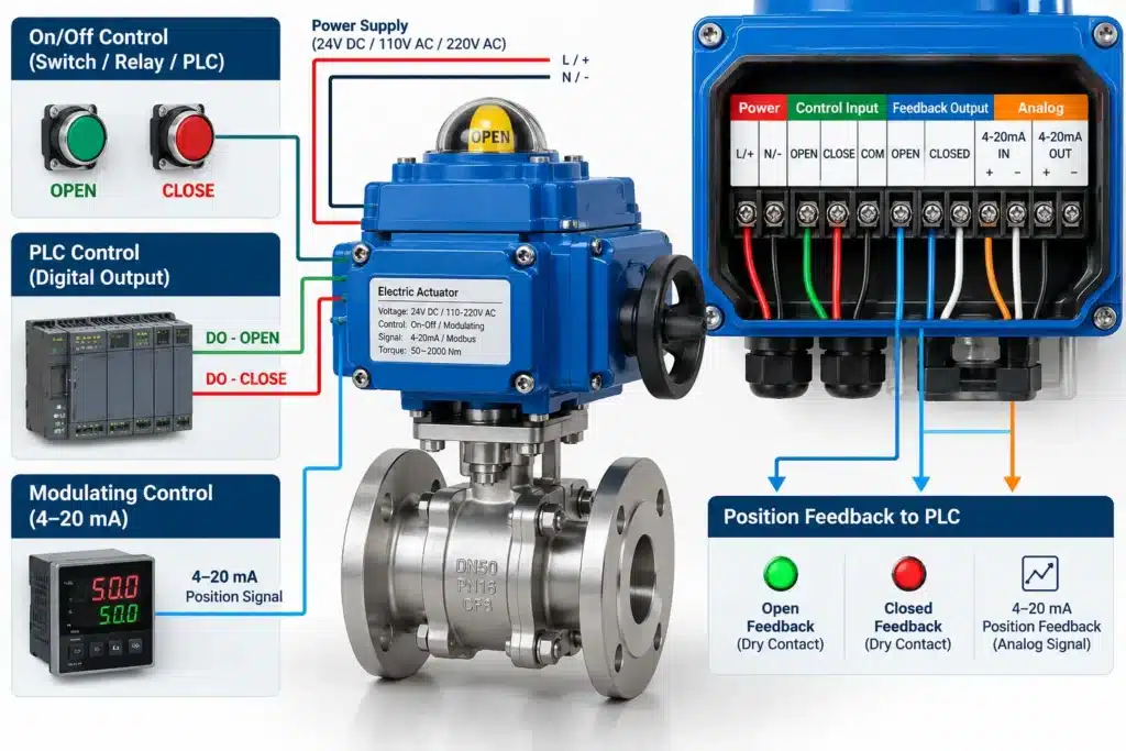
What Are the Main Ways to Control a Motorized Ball Valve?
The control method depends on whether the valve needs simple on-off movement, automatic sequencing or continuous flow regulation.
| Control Method | How It Works | Typical Application |
|---|---|---|
| Local Manual Control | Local electrical pushbuttons or selector switches command the actuator | Commissioning and maintenance |
| On-Off Electrical Control | Switches or relays provide open and close commands | Automatic pipeline isolation |
| PLC / DCS Control | Controller outputs operate the valve and monitor feedback | Pump skids and process automation |
| 4–20 mA Modulating Control | An analogue signal specifies an intermediate valve position | Flow and pressure regulation |
| Digital Communication | Supported protocols transmit commands and status data | Centralized industrial automation |
Local Electrical Control
Local control is useful during commissioning, inspection and maintenance. An actuator equipped with local OPEN, CLOSE and STOP controls can be operated at the installation location without sending commands from the central PLC.
Some actuators provide a LOCAL/OFF/REMOTE selector. The selected mode determines whether remote commands are accepted. A valve that does not respond to the PLC may simply be in local mode, although this should be verified before further troubleshooting.
On-Off Remote Control
On-off control is the most common arrangement for motorized ball valves used in isolation service. The controller commands the actuator to move to the fully open or fully closed position.
The command may come from a pushbutton, level controller, pressure switch, relay system or PLC output. Depending on actuator design, the command can be maintained until travel is completed or accepted as a momentary instruction by internal control logic.
Commande modulante
Modulating control is used when the motorized ball valve must remain at intermediate positions rather than simply open and close.
A control signal represents the required valve position. The actuator compares that target with the measured position and moves the ball until the difference falls within the configured positioning tolerance.
This control mode should be paired with a valve designed for throttling, such as a correctly sized V-port ball valve. A conventional round-port isolation ball valve is generally less suitable for precise continuous flow regulation.
How to Wire a Motorized Ball Valve for Electrical Control
Wiring is often the first practical challenge when installing a motorized ball valve. Different actuators use different terminal arrangements, and the number of wires alone does not reliably identify the control method.
Before connecting the actuator, confirm the rated supply voltage, operating current, starting current, command-input type, internal limit switches and feedback terminals.
2-Wire Motorized Ball Valve Control
Two-wire designs can use different operating principles. Certain actuators use power-on and power-off behavior with an internal return mechanism. Others use polarity reversal or a dedicated drive arrangement to change motor direction.
These designs are not electrically interchangeable. Removing power from a standard reversible actuator does not necessarily cause the valve to close. A defined return action requires a suitable actuator mechanism or stored-energy system.
3-Wire Motorized Ball Valve Control
Some three-wire actuators provide a common connection and separate opening and closing command connections. In these designs, the controller applies the specified control signal to the appropriate input.
The actuator may contain internal travel limits and motor switching components. However, other three-wire models use different configurations, so the wiring diagram must be checked before installation.
Opening and closing signals should not be applied simultaneously unless the actuator manufacturer explicitly defines a safe method for handling conflicting commands.
Separate Power and Control Wiring
Larger industrial motorized ball valves commonly separate motor power from the command and feedback circuits. This allows the motor to receive the required electrical supply while the PLC uses suitable control interfaces to command operation.
Such arrangements may include dedicated OPEN, CLOSE, STOP, common, fault and end-position terminals. The exact terminal functions depend on the selected actuator.
| Electrical Connection | Purpose | Important Check |
|---|---|---|
| Alimentation électrique | Operates motor and electronics | Voltage, frequency and current rating |
| OPEN Input | Requests valve opening | Input voltage and contact type |
| CLOSE Input | Requests valve closing | Input voltage and command logic |
| STOP Input | Interrupts travel where supported | Operating and priority logic |
| OPEN Feedback | Confirms full-open position | Contact rating and polarity |
| CLOSED Feedback | Confirms full-closed position | Contact rating and polarity |
| Analogue Signal | Provides position command or feedback | 4–20 mA / 0–10 V interface and scaling |
Never connect PLC outputs directly to actuator motor terminals unless the actuator and output circuit are specifically designed for that arrangement. Electrical installation should be performed by qualified personnel with the equipment isolated and the approved wiring diagram available.
How to Control a Motorized Ball Valve with a PLC
PLC control allows a motorized ball valve to operate automatically according to process conditions instead of relying on a local switch.
In a typical on-off application, the PLC sends opening or closing commands through compatible digital output circuits. The actuator provides end-position feedback, allowing the PLC to determine whether the valve reached its intended position.
Depending on the actuator interface, the PLC may command the valve through voltage-rated digital inputs or through interposing relays that provide isolated contacts. The selected interface must be compatible with the actuator control circuit.
Example PLC Input and Output Arrangement
| PLC Signal | Fonction | Example Use |
|---|---|---|
| Digital Output 1 | OPEN Command | Requests opening |
| Digital Output 2 | CLOSE Command | Requests closing |
| Digital Input 1 | OPEN Confirmation | Confirms fully open |
| Digital Input 2 | CLOSED Confirmation | Confirms fully closed |
| Digital Input 3 | Fault or Available Status | Identifies actuator fault or unavailability |
The signal list above is an example of a control architecture, not a terminal-to-terminal wiring diagram. Some actuators use a single directional control input, integrated control electronics or fieldbus communication instead of separate OPEN and CLOSE inputs.
Example Pump-System PLC Sequence
Consider a motorized ball valve used to isolate a pump discharge line. The control system may need the valve to reach its required position before the pump can start.
The PLC receives a pump-start request and checks that process conditions permit startup.
The PLC sends the required opening command to the motorized ball valve.
The actuator moves the valve toward its fully open position.
The open-position feedback becomes active when the valve reaches the configured end position.
After the required valve feedback and other interlocks are confirmed, the PLC permits pump startup.
If the valve fails to reach the required position within the permitted time, the PLC inhibits startup and generates an alarm.
This is an example for a system requiring the valve open before startup. Actual pump sequences depend on pump type, hydraulics, check-valve design and the approved operating philosophy.
Preventing Conflicting Commands
The PLC program should prevent incompatible opening and closing commands from being active together. Command arbitration should also define the priority of local operation, remote operation, STOP, protective interlocks and emergency shutdown.
If a reversing motor circuit is used, appropriate electrical and mechanical interlocking may also be required. PLC logic alone should not be treated as the only protection against unsafe motor reversal.
How to Control a Motorized Ball Valve with a 4–20 mA Signal
A 4–20 mA signal is commonly used when the motorized ball valve must regulate flow or pressure rather than perform simple on-off isolation.
In a typical configuration, the process controller sends an analogue position command to a modulating actuator. The actuator measures its actual position, compares it with the commanded position and drives the motor until the required angle is reached.
The signal relationship can be configured in different ways. In one common arrangement, 4 mA represents fully closed and 20 mA represents fully open.
| Command Signal | Example Valve Position | Actuator Response |
|---|---|---|
| 4 mA | 0% open | Moves toward closed position |
| 8 mA | 25% open | Moves toward quarter travel |
| 12 mA | 50% open | Moves toward mid travel |
| 16 mA | 75% open | Moves toward three-quarter travel |
| 20 mA | 100% open | Moves toward fully open |
This table illustrates linear position scaling. Some actuators allow reversed action, custom limits or alternative command relationships.
Importantly, 50% valve travel does not necessarily mean 50% flow. Actual flow depends on the valve’s inherent flow characteristic, available pressure drop and the hydraulic characteristics of the pipeline.
Using a V-Port Motorized Ball Valve for Flow Regulation
A V-port motorized ball valve is a more suitable option when proportional flow adjustment is required. Its V-shaped opening provides a more progressive relationship between ball position and effective flow area than a typical round-port isolation ball valve.
In a pump discharge application, a flow transmitter can measure the actual process flow. The PLC or DCS compares the measured flow with the required setpoint and adjusts the valve command accordingly.
For example, when the measured flow exceeds the target, the process controller may command the valve toward a more closed position. When the flow falls below the target, the controller may move it toward a more open position.
Actual control direction and stability depend on the process configuration. PID settings, valve sizing, actuator positioning resolution and the process response time must be considered together.
Why Control Deadband Matters
A modulating actuator should not continually move in response to insignificant signal variations. Positioning deadband defines a small permissible difference between commanded and actual position.
If the deadband is too narrow, the actuator may hunt continuously and create excessive motor starts and mechanical wear. If it is too wide, the valve may not respond accurately enough for the process.
Deadband and controller tuning should therefore be adjusted according to the actuator duty rating and required control accuracy.
Other Control Signals and Digital Communication
Depending on actuator electronics, motorized ball valves may also support 0–10 V commands or industrial digital communication.
A suitable communication-enabled actuator may exchange valve commands, position information, operating status and diagnostic data over a protocol such as Modbus.
Digital communication should only be specified when the exact actuator model supports the required interface, protocol configuration and network architecture.
For a modulating application, both the actuator and the ball valve must be suitable for proportional control. A standard on-off electric ball valve should not be assumed to support 4–20 mA simply because it contains an electric motor.
Motorized Ball Valve Position Feedback and Control Interlocks
Position feedback allows the control system to determine whether a motorized ball valve is actually open, closed or at a commanded intermediate position.
For an on-off valve, feedback commonly comes from end-position switches or configurable actuator relays. The controller can use these signals to confirm completion of an opening or closing operation.
Modulating actuators may provide a continuous position signal, often 4–20 mA, representing the measured actuator position.
Open and Closed Limit Switches
Limit switches indicate that the actuator has reached a configured end position. Their signals can be used to stop or confirm travel according to the actuator design.
For example, a PLC may require a fully open signal before allowing a transfer pump to operate. Similarly, a chemical-feed sequence may require a valve to be confirmed closed before another process step begins.
Travel Time Monitoring
A useful control system compares the expected valve travel time with the actual response.
If the valve normally requires several seconds to open but the open feedback does not arrive within the configured timeout, the PLC can report an abnormal operation.
Possible causes include insufficient actuator torque, mechanical obstruction, incorrect wiring, motor protection operation or failed position feedback.
The timeout should accommodate the actuator’s rated operating time, control delays and site conditions without allowing an abnormal operation to remain undetected indefinitely.
Interlocks and Emergency Stop Conditions
A motorized ball valve can be incorporated into interlocks that prevent unsafe operation. Typical conditions include pump availability, line pressure, tank level, emergency shutdown status or confirmation of other valve positions.
The control logic should define which commands take priority and whether the actuator must stop, remain in position or move toward a specified state when an interlock becomes active.
What Happens to a Motorized Ball Valve During Power Failure?
Power failure behavior is an important part of motorized ball valve control, especially in unattended or critical industrial systems.
A conventional electric actuator normally requires electrical power to move the valve. If supply power is lost, a standard actuator may remain at its current position unless it contains a suitable stored-energy or fail-safe arrangement.
Some actuator configurations can provide a controlled return movement using a battery, capacitor system, spring mechanism or another approved source of stored energy.
Fail-Close Control
Fail-close operation is used where stopping the flow is the preferred response to a power or control-system failure.
Certain chemical-transfer or process-isolation applications may require this behavior, subject to the process safety design.
Fail-Open Control
Fail-open operation is selected when maintaining the flow path is more important than immediate isolation.
Some cooling or emergency-service circuits may use this philosophy, provided the equipment and process design support it.
Stay-in-Position Control
In other applications, the safest response may be for the valve to remain in its last position. This can avoid unnecessary flow interruption or unexpected valve movement.
The required fail position must be determined from the process conditions rather than assuming that every motorized valve should close when power is lost.
Emergency shutdown commands, loss of communication and complete loss of actuator power are different events. An actuator may respond correctly to an electrical CLOSE command but be unable to move after losing its power supply unless an appropriate fail-safe system is installed.
How Fast Should a Motorized Ball Valve Open and Close?
Motorized ball valve speed should be selected from the process requirements rather than choosing the fastest actuator available.
In some compact industrial systems, an actuator with a selectable opening and closing time in the range of 3–10 seconds may be useful for automatic sequencing or relatively fast valve movement.
However, that speed range is not appropriate for every application. Large-diameter liquid pipelines, long water-transfer systems and high-flow pump stations may require substantially different valve movement characteristics.
Closing a valve too rapidly can cause a sudden change in liquid velocity and contribute to water hammer. This pressure transient may affect pipelines, pumps, supports and other equipment.
On the other hand, a valve that operates too slowly may delay isolation or fail to meet an automated process sequence.
How Actuator Torque Affects Control Reliability
The motorized ball valve actuator must provide sufficient torque to move the ball under the maximum realistic operating conditions.
Ball valve torque depends on the valve size, pressure differential, seat material, fluid temperature, friction and operating history.
Breakaway torque can be particularly important when a valve remains in one position for extended periods. Deposits, seat friction or process pressure may increase the force required to begin movement.
An actuator that is undersized may fail to start movement, stop before reaching its limit or trigger overload protection.
Actuator selection must also account for the intended operating frequency. A valve used for continuous modulation may require a different actuator duty rating from one that opens and closes only a few times per day.
Motorized ball valve torque, operating speed and duty cycle should be selected together. A high-torque actuator does not automatically provide faster movement or better modulating performance.
How Motorized Ball Valves Are Controlled in Industrial Applications
The correct control strategy depends on the role of the motorized ball valve within the industrial process.
Water Treatment
Motorized ball valves can automate water-transfer lines, filter systems, chemical dosing circuits and tank isolation. PLC control may use tank level, pressure or operating sequences to determine when each valve should open or close.
Where a valve is used for modulating water flow, valve sizing and closing speed should be checked to prevent unstable regulation and unnecessary pressure transients.
Pump Systems and Pump Skids
Motorized ball valves can be linked to pump startup and shutdown procedures. The controller may require confirmed valve position before permitting a pump to operate.
On-off valves are suitable for isolation, while appropriately sized V-port motorized ball valves can be used in flow-control or bypass applications.
Pétrole et gaz
Motorized ball valves are used in selected oil and gas applications requiring remote isolation and automated pipeline operation. Control requirements can include status monitoring, emergency shutdown integration and communication with centralized control systems.
Actuator enclosure protection, hazardous-area suitability, valve pressure rating and the required fail-safe behavior must be defined for the installation.
Metallurgy
Metallurgical facilities use motorized valves in cooling-water networks, process utilities and automated production equipment. Reliability can be affected by heat, dust, environmental exposure and frequent operating cycles.
The actuator should be selected according to the installation environment and required automation duty.
Chemical Processing
Chemical processing applications may require automatic fluid isolation, tank routing or proportional flow control. The control system can incorporate tank-level signals, pressure conditions and process interlocks.
Valve material compatibility and the correct fail position are especially important when handling hazardous or corrosive media.
How to Commission a Motorized Ball Valve Control System
Commissioning verifies that the actuator, valve body, electrical supply and control system operate together as intended.
The valve should be inspected and tested under a controlled procedure before being placed into automatic service.
Confirm the valve size, pressure rating, actuator model, supply voltage and approved wiring diagram. Isolate electrical and process energy before connection or adjustment.
Inspect wiring, protective grounding, cable glands, terminations and the mechanical connection between actuator and valve stem.
Verify local and remote operating modes, then test valve movement under a safe commissioning procedure.
Confirm that the opening and closing commands move the valve in the intended direction and that the travel limits are correctly configured.
Verify OPEN, CLOSED and fault feedback at the controller. For modulating actuators, calibrate the command and position-feedback signals.
Test command priority, travel timeouts, permissive interlocks and the specified response to control-signal loss or emergency conditions.
After safe functional testing, verify the complete valve and process sequence under approved operating conditions, monitoring pressure, flow and actuator behavior.
Common Motorized Ball Valve Control Problems
| Problème | Cause possible | What to Check |
|---|---|---|
| Valve does not move | Power loss, incorrect mode, control fault or overload | Supply, control mode and diagnostics |
| Valve moves in the wrong direction | Incorrect command mapping or configuration | Actuator control settings and wiring |
| Valve stops before reaching the limit | Torque overload, mechanical restriction or limit setting | Valve condition and actuator setup |
| PLC does not confirm position | Feedback wiring or limit-switch problem | Status contacts and PLC inputs |
| Modulating valve keeps moving | Deadband too narrow, unstable PID or signal noise | Positioner calibration and controller tuning |
| Valve does not reset after power failure | No stored-energy function or incorrect configuration | Actual fail-safe actuator capability |
| Unexpected pressure surge | Valve movement too fast for hydraulic system | Closing sequence and surge analysis |
Troubleshooting should begin with the actual actuator fault indication and the approved electrical drawings. Repeatedly energizing a stalled actuator without identifying the cause can damage the motor, gearbox or valve components.
Foire aux questions
How do you control a motorized ball valve?
A motorized ball valve can be controlled through a local switch, electrical relay, PLC, DCS or compatible communication system. On-off actuators respond to opening and closing commands, while modulating actuators can follow analogue position signals such as 4–20 mA.
Can I control a motorized ball valve with a PLC?
Yes. A PLC can issue compatible opening and closing commands and read valve-position feedback. Depending on the actuator, it may use digital outputs, interposing relays, analogue signals or an industrial communication interface.
How does a 3-wire motorized ball valve work?
Certain three-wire actuators use a common connection and separate opening and closing inputs. However, wiring conventions differ between models, so the actuator’s approved electrical diagram must be followed.
Can a motorized ball valve be controlled with 4–20 mA?
Yes, when equipped with a compatible modulating actuator and positioner. The signal represents a commanded valve position, which the actuator follows within its configured positioning tolerance.
Can a motorized ball valve stop halfway?
A modulating actuator can stop at intermediate positions. Some on-off actuators also support an intermediate STOP command, but this does not automatically make the valve suitable for accurate continuous flow control.
Does a motorized ball valve close automatically during power failure?
Not necessarily. A standard electric actuator may remain in its last position. Automatic fail-close or fail-open operation requires a suitable fail-safe design with the necessary stored-energy or return mechanism.
Can a motorized ball valve be controlled by Modbus?
Yes, if the actuator is equipped with a compatible Modbus interface. Supported commands, status information and communication settings depend on the exact actuator model.
What is the difference between on-off and modulating motorized ball valves?
An on-off motorized ball valve normally moves between fully open and fully closed positions. A modulating valve can move to intermediate positions according to an analogue or digital setpoint. The ball valve design must also be suitable for the intended control duty.
How do I know if a motorized ball valve is fully open?
Use the actuator’s open-position feedback or a suitably configured position transmitter. An opening command alone does not confirm the actual valve position.
What voltage is required to control a motorized ball valve?
Common industrial actuator supplies include 24V DC, 110V AC and 220V AC, although other options are available. The actuator’s supply voltage must be distinguished from its command-input and feedback-signal ratings.
Conclusion
Controlling a motorized ball valve requires selecting the correct interface between the electric actuator and the control system. Simple isolation can be performed through electrical opening and closing commands, while more complex industrial systems use PLC logic, valve-position feedback and interlocks.
When proportional flow regulation is required, a modulating actuator can follow a 4–20 mA or other supported position command. A correctly sized V-port ball valve is generally more appropriate for this application than a conventional round-port isolation valve.
Electrical wiring must match the specific actuator design. Supply voltage, command inputs and feedback outputs should always be checked separately, and neither two-wire nor three-wire connections should be assumed to follow a universal convention.
Valve opening speed, actuator torque, travel limits, fail-safe behavior and commissioning procedures are equally important for reliable operation. In pump systems, water treatment, oil and gas and other industrial applications, the best results come from treating the motorized ball valve and its control logic as one engineered system.