


Industrial Valve Automation Guide
Motorized Valve: Types, Working Principle & Selection Guide
A motorized valve combines a valve body with an electric actuator to automatically open, close, or regulate liquid, gas, steam, and other media in a pipeline. Common types include motorized ball, butterfly, gate, globe, control, and zone valves. This guide explains how motorized valves work, the main types, on-off vs. modulating control, typical applications, and the key parameters engineers and buyers should check before selection.
Quick Answer
Choose the valve body for the media and flow requirement, then match the electric actuator to the required torque, power supply, control signal, duty cycle, and installation environment. For shutoff service, ball and butterfly valves are common. For accurate regulation, globe valves and purpose-designed motorized control valves are usually more suitable.
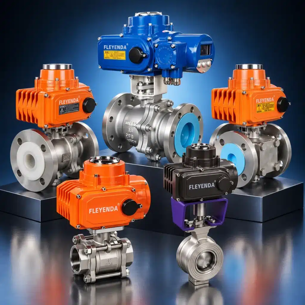
What Is a Motorized Valve?
A motorized valve is a valve operated by an electric actuator instead of by a handwheel or lever. The valve body controls the fluid, while the actuator provides the mechanical force needed to move the ball, disc, gate, plug, or stem. A controller, thermostat, PLC, building management system, or remote switch sends an electrical command to the actuator, which moves the valve to the required position.
Motorized valves can be used for simple on-off isolation or for modulating control. In on-off service, the valve moves between fully open and fully closed positions. In modulating service, the actuator can stop at intermediate positions to regulate flow, pressure, temperature, level, or mixing ratio.
This combination of remote operation, repeatable positioning, feedback, and system integration makes motorized valves widely used in HVAC, water treatment, chemical processing, irrigation, power generation, marine systems, food processing, and industrial automation.
Quick Definition
A motorized valve is an electrically actuated valve used to automatically open, close, divert, or regulate pipeline flow. The correct selection depends on both the valve body and the electric actuator.
How Does a Motorized Valve Work?
A motorized valve works by converting electrical energy into mechanical motion. The electric actuator normally contains a motor, gear train, limit switches, torque protection components, and, depending on the model, a control board and position feedback module. When the actuator receives power or a control signal, the motor rotates and the gear mechanism reduces speed while increasing output torque.
For quarter-turn valves such as ball valves and butterfly valves, the actuator normally rotates the valve shaft through approximately 90 degrees. For multi-turn valves such as gate valves, the actuator rotates the stem through multiple turns. For linear control valves, the actuator moves the stem up or down to change the opening between the plug and seat.
Limit switches stop the actuator at the fully open and fully closed positions. Torque switches or electronic torque protection can help prevent damage if the valve becomes jammed or operating resistance is excessive. Modulating actuators may accept signals such as 0–10 VDC, 2–10 VDC, or 4–20 mA, while intelligent actuators may provide position feedback and industrial communication options.
On-Off Control
The valve moves fully open or fully closed. It is commonly used for isolation, zone control, equipment protection, and automatic switching.
Modulating Control
The valve can stop at intermediate opening positions to regulate flow, pressure, temperature, or another process variable.
Position Feedback
The actuator sends open/close status or continuous position feedback to the controller, making monitoring and fault detection easier.
Motorized Valve Types at a Glance
The term motorized valve describes the actuation method, not one specific valve design. The best valve type depends on whether the application requires tight shutoff, low pressure drop, large pipe size, accurate throttling, or compact installation.
| Valve Type | Best Suited For | Typical Control | Key Selection Point |
|---|---|---|---|
| Motorized Ball Valve | Reliable shutoff, low pressure loss, frequent switching | On-off or modulating | Seat material, bore design, torque, media compatibility |
| Motorized Butterfly Valve | Medium and large pipelines, HVAC and water systems | On-off or modulating | Disc/seat material, differential pressure, actuator torque |
| Motorized Gate Valve | Full-bore isolation and low pressure drop | Mainly on-off | Multi-turn actuator sizing, stem thrust/torque, operating frequency |
| Motorized Globe Valve | Stable throttling and process regulation | Mainly modulating | Flow coefficient, pressure drop, control characteristic |
| Motorized Control Valve | Closed-loop regulation of flow, pressure, or temperature | Modulating | Valve sizing, actuator resolution, control signal, feedback accuracy |
| Motorized Zone Valve | HVAC zoning and small hydronic circuits | Usually on-off | Voltage, pipe size, close-off pressure, fail position |
Quick selection: Ball valves are commonly chosen for tight shutoff, butterfly valves for larger pipe sizes, gate valves for full-bore isolation, and globe/control valves when accurate flow regulation is more important than minimum pressure loss.
Main Types of Motorized Valves
Different valve bodies can be combined with electric actuators to meet different working conditions. The most common motorized valve configurations are described below.
Motorized Ball Valve
A motorized ball valve uses a hollow ball as the shutoff element. When the bore in the ball aligns with the pipeline, fluid passes through with relatively low pressure loss. Rotating the ball by 90 degrees blocks the passage. This design provides compact construction, reliable sealing, and fast quarter-turn operation.
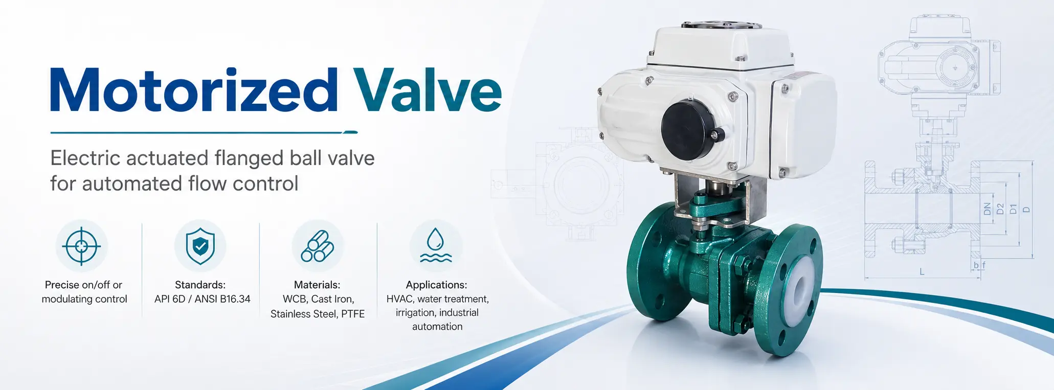
Motorized ball valves are widely used for water, air, oil, HVAC systems, irrigation, water treatment equipment, and general industrial pipelines. Stainless steel versions are often selected for corrosive or clean-service applications, while flanged motorized ball valves are suitable for larger industrial pipelines where strong connections and maintenance access are important.
Motorized Butterfly Valve
A motorized butterfly valve uses a disc mounted on a shaft. The actuator rotates the disc to open, close, or throttle the flow. Butterfly valves are especially practical for medium and large pipe diameters because they are lighter, more compact, and often more economical than large ball or gate valves.
They are frequently used in HVAC chilled water, cooling towers, wastewater treatment, fire protection, seawater systems, and industrial water distribution. Depending on the seat design and actuator type, a motorized butterfly valve can be used for on-off or modulating service.
Motorized Gate Valve
A motorized gate valve uses a gate or wedge that moves vertically to isolate the pipeline. When fully open, the gate is lifted out of the flow path, giving a low pressure drop. This makes motorized gate valves suitable for water supply networks, oil and gas pipelines, power plants, and other large industrial systems.
Because gate valves require multiple stem rotations, they normally use multi-turn electric actuators. They are generally selected for isolation rather than frequent throttling, because prolonged partial opening can lead to vibration, erosion, and unstable control.
Motorized Globe Valve
A motorized globe valve is designed for more stable throttling. Its internal geometry forces the media through a controlled opening between the plug and seat. Compared with ball and gate valves, globe valves normally have a higher pressure drop but offer better regulation characteristics.
Motorized globe valves are often used in steam, hot water, chilled water, chemical dosing, and process control loops. When combined with a modulating electric actuator, they can continuously adjust the valve opening according to controller demand.
Motorized Control Valve
A motorized control valve is designed specifically for regulating a process variable. It may use a globe valve, characterized ball valve, butterfly valve, or another valve body, but accurate positioning and repeatable control are the main priorities.
In a closed-loop system, a sensor measures the process condition, the controller calculates the required correction, and the motorized control valve changes its opening to maintain the target value. Important factors include flow coefficient, rangeability, actuator resolution, response time, feedback accuracy, and compatibility with the controller signal.
Motorized Zone Valve
A motorized zone valve is commonly used in HVAC and plumbing systems to divide a building or hydronic system into independently controlled zones. A thermostat or controller opens the valve when heating or cooling is required and closes it after the setpoint is reached.
Zone valves are usually compact and designed for smaller pipe sizes. Selection should consider voltage, pipe connection, close-off pressure, flow capacity, spring return or fail position, and compatibility with the thermostat or building control system.
Motorized Valve vs. Motorized Control Valve
A motorized valve is a broad category covering any valve operated by an electric actuator. A motorized control valve is a more specific configuration designed primarily for accurate and repeatable modulation in a control loop. In other words, every motorized control valve is motorized, but not every motorized valve is intended for precise process control.
| Item | Motorized Valve | Motorized Control Valve |
|---|---|---|
| Main Purpose | Automatic opening, closing, diversion, or basic modulation | Continuous regulation of a process variable |
| Typical Operation | On-off, floating, or modulating | Usually modulating |
| Common Signals | Relay/open-close commands, floating control, analog signals | 0–10 VDC, 4–20 mA, digital/fieldbus control depending on actuator |
| Key Engineering Focus | Shutoff, torque, pressure/temperature rating, material compatibility | Valve sizing, Cv/Kv, rangeability, resolution, stability, feedback accuracy |
| Typical Applications | Isolation, zoning, switching, equipment protection | Flow, pressure, temperature, level, and process regulation |
Selection Tip
If the application only needs reliable automatic shutoff, a standard on-off motorized valve is often sufficient. If the controller must continuously adjust the valve position to hold a target flow, pressure, or temperature, specify a properly sized motorized control valve with a modulating actuator and suitable feedback.
Technical Parameters and Materials to Check
Motorized valve selection should be based on the complete valve-and-actuator assembly. The valve must match the pipeline, pressure, temperature, media, connection standard, and shutoff or control requirement. The actuator must then provide enough torque or thrust and support the required power supply, control signal, duty cycle, protection level, and feedback functions.
The following table uses a typical motorized flanged ball valve as an example of the kinds of engineering standards that may need to be confirmed during selection.
| Item | Technical Parameter | Standard / Specification |
|---|---|---|
| Design Basis | API, ANS | Engineering design reference |
| Design Standard | API 6D, ANSI B16.34 | Valve design and pressure-temperature rating |
| Face-to-Face Dimension | API 6D, ANSI B16.10 | Structural length and installation dimension |
| Connecting Flange Size | ANSI B16.5 | Flanged pipeline connection standard |
| Test and Inspection | API 6D, API 598 | Pressure test, sealing test, and valve inspection |
Note: The structural length and connection flange size of ball valve series can be designed and manufactured according to user requirements. Confirm the actual project standard before ordering.
| No. | Part Name | Material |
|---|---|---|
| 1 | Body | Cast Iron, WCB, Stainless Steel |
| 2 | Ball | Cast Iron, WCB, Stainless Steel |
| 3 | Lining Material / Seat | PTFE |
| 4 | Packing | PTFE |
| 5 | Cap | Cast Iron, WCB, Stainless Steel |
| 6 | Stem | Stainless Steel 304, 316 |
| 7 | Connecting Set | Stainless Steel 304, 316 |
| 8 | Screw | Stainless Steel 304, 316 |
| 9 | Hand Gear | Plastic |
| 10 | Electric Actuator | On/Off Type, Intelligent Type, Multi-Turn Type, Explosion-Proof Type |
Material selection must match the media and operating environment. Cast iron and WCB are commonly considered for general industrial service, while stainless steel is often preferred for corrosive or clean-service applications. Seat and packing materials such as PTFE are selected according to chemical compatibility, temperature, pressure, and required leakage performance.
Where Are Motorized Valves Used?
Motorized valves are used wherever pipeline flow needs to be controlled automatically from a local controller or a larger automation system. The exact valve body and actuator configuration varies by industry, but the engineering goal is the same: reliable, repeatable, remotely controlled operation.
In HVAC systems, motorized valves control chilled water, hot water, condenser water, steam, and glycol circuits. Building automation systems can open, close, or modulate valves according to temperature demand, pressure differential, equipment status, or operating schedule.
In water and wastewater treatment, they are used for filtration, backwash, raw-water intake, chemical dosing, sludge discharge, and distribution. Automated operation is particularly useful where valves are large, difficult to access, or required to follow repeated process sequences.
In chemical and process industries, motorized valves support dosing, mixing, batching, transfer, isolation, and process regulation. Material compatibility, actuator enclosure protection, and hazardous-area requirements become especially important in these environments.
Other common applications include irrigation, food and beverage processing, power plants, marine systems, oil and gas facilities, fire protection, utility systems, and general industrial automation.
Typical Application Areas
- HVAC chilled water, hot water, condenser water, glycol, and steam systems
- Water treatment, wastewater treatment, filtration, and backwash systems
- Smart irrigation, agricultural watering, greenhouse, and landscape systems
- Chemical dosing, mixing, batching, and industrial process pipelines
- Food and beverage processing and clean-service pipelines
- Power plants, marine engineering, oil and gas, and general industrial automation
How to Select the Right Motorized Valve
Selecting the right motorized valve requires more than confirming the pipe size. A reliable selection should begin with the process conditions, then match the valve body, seat, connection, and electric actuator to the actual duty.
1. Process Conditions
Confirm the medium, concentration, viscosity, solids content, working pressure, differential pressure, and operating temperature.
2. Valve Requirements
Confirm DN/NPS size, valve type, connection standard, body material, seat material, pressure class, required leakage performance, and flow capacity.
3. Actuator Requirements
Confirm torque or thrust, power supply, on-off or modulating control, control signal, feedback, duty cycle, manual override, IP rating, and hazardous-area requirements.
Media compatibility comes first. Water, steam, compressed air, seawater, oil, acid, alkali, glycol, chlorine solution, and food-grade liquids can require different body, trim, seat, and packing materials. The maximum pressure and temperature must also be checked together with possible pressure surges or unusual operating conditions.
Control requirement is another major factor. If the application only needs automatic shutoff, an on-off motorized valve is usually sufficient. If the process requires continuous regulation, choose a modulating actuator and a valve body with suitable control characteristics. The actuator signal must match the controller output.
Actuator sizing should be based on real operating conditions rather than no-load valve movement. Differential pressure, seat friction, media viscosity, scaling, temperature, aging, and operating frequency can all increase the required torque or thrust. A suitable safety margin should be applied when matching the actuator to the valve.
Installation environment also matters. Outdoor, wet, dusty, corrosive, marine, or hazardous locations may require enhanced enclosure protection, corrosion-resistant coatings or housings, special cable sealing, or explosion-proof actuator construction.
Professional Selection Checklist
- Medium, concentration, viscosity, solids content, and corrosion characteristics
- Pipe size (DN/NPS), connection type, flange standard, and pressure class
- Working pressure, differential pressure, maximum pressure, and temperature range
- Valve type: ball, butterfly, gate, globe, control, or zone valve
- Body, trim, seat, packing, and stem materials
- Required flow coefficient (Cv/Kv) or design flow rate when applicable
- On-off, floating, or modulating actuator function
- Power supply, wiring method, control signal, and feedback requirement
- Required actuator torque/thrust, operating speed, duty cycle, and manual override
- Fail-safe or fail-position requirement, if the process requires one
- Enclosure protection, outdoor duty, corrosion protection, or explosion-proof requirement
- Applicable design, connection, testing, certification, and project standards
Information to Send for Valve Selection or Quotation
For a faster and more accurate recommendation, provide the medium, pipe size, pressure, temperature, connection standard, body/seat material, required valve function, power supply, control signal, feedback requirement, installation environment, and quantity. For modulating service, also provide the design flow rate and available differential pressure whenever possible.
Advantages of Using a Motorized Valve
The main advantage of a motorized valve is automatic control. Once connected to a control system, the valve can operate according to real-time commands without manual intervention. This supports centralized operation, remote control, repeatable sequencing, and better integration with modern automation systems.
Motorized valves also improve repeatability. Defined electrical commands and mechanical travel limits help the valve return to known positions, while optional position feedback allows the control system to confirm whether the commanded movement was completed.
They can also support system safety by integrating with pressure switches, level sensors, alarms, leak detection, emergency shutdown logic, and remote monitoring. In locations where compressed air is not available, an electric actuator can simplify automation infrastructure compared with pneumatic actuation.
Common Problems and Maintenance Tips
Actuator overload can occur when the actuator is undersized or when valve operating torque increases because of debris, scaling, high differential pressure, temperature changes, or long periods without operation. Repeated operation above the actuator rating can damage the motor, gears, or control electronics.
Valve leakage may result from seat wear, incompatible sealing materials, trapped particles, poor alignment, pipeline stress, or incorrect installation. Flushing the pipeline before commissioning helps reduce damage caused by welding slag, sand, rust, and other contaminants.
Electrical faults can occur because of water ingress, dust, corrosive vapor, unstable voltage, loose cable glands, incorrect wiring, or signal interference. Installation should follow the actuator wiring diagram and the required enclosure and grounding practices.
Routine maintenance should include visual inspection, wiring checks, open-close testing, leakage inspection, verification of feedback signals, and observation of abnormal noise or operating time. Critical installations may also benefit from recording valve cycles, actuator alarms, and changes in operating time to identify wear before a complete failure occurs.
Frequently Asked Questions About Motorized Valves
What is the main function of a motorized valve?
The main function of a motorized valve is to automatically control pipeline flow. Depending on the valve and actuator design, it can open, close, divert, or modulate the flow according to an electrical command.
What is the difference between an on-off motorized valve and a modulating motorized valve?
An on-off motorized valve moves between fully open and fully closed positions. A modulating motorized valve can stop at intermediate positions to regulate flow, pressure, temperature, or another process variable.
Is a motorized valve the same as a motorized control valve?
Not exactly. Motorized valve is the broader term for any valve operated by an electric actuator. A motorized control valve is designed specifically for more accurate and repeatable regulation, usually with a modulating actuator and a properly sized control-valve body.
Which motorized valve is commonly used for large pipelines?
Motorized butterfly valves are commonly considered for medium and large water or HVAC pipelines because they are compact and relatively light. Motorized gate valves may be selected when full-bore isolation and very low pressure drop are important.
Can a motorized valve be used outdoors?
Yes, provided the electric actuator and electrical connections have suitable protection for the installation environment. Outdoor, humid, corrosive, marine, or hazardous locations may require higher enclosure protection, improved corrosion resistance, special cable sealing, or explosion-proof construction.
What information is needed to select a motorized valve?
At minimum, provide the medium, pipe size, pressure, temperature, connection type, valve function, preferred materials, power supply, control mode, control signal, feedback requirement, and installation environment. Modulating applications should also include flow and differential-pressure information when available.
Conclusion
A motorized valve combines a valve body with an electric actuator to provide automatic, remote, and repeatable control of pipeline media. Ball valves are commonly selected for reliable shutoff, butterfly valves for larger pipelines, gate valves for full-bore isolation, and globe or control valves for more accurate regulation.
For engineers, contractors, equipment manufacturers, and industrial buyers, correct selection should consider media compatibility, pipe size, pressure, temperature, valve type, connection standard, body and seat materials, actuator torque or thrust, power supply, control signal, feedback, duty cycle, enclosure protection, and applicable project standards.
When these parameters are matched correctly, a motorized valve can improve automation efficiency, reduce manual operation, support safer system control, and provide more consistent long-term performance.