


Valve Actuator: Types & Selection Guide
A valve actuator is a mechanical device that automatically opens, closes, or positions an industrial valve. By converting electrical power, compressed air, or hydraulic pressure into motion, a valve actuator allows flow-control systems to operate without continuous manual intervention.
Valve actuators are widely used in water treatment, oil and gas, chemical processing, pump systems, and industrial production. However, selecting the correct actuator requires more than matching it to the nominal valve size.
Engineers must consider the valve’s operating torque or thrust, movement type, duty cycle, available power, control signals, mounting dimensions, environmental protection, and required failure response.
This valve actuator selection guide explains the main actuator types, how to size them, and which technical specifications industrial buyers should confirm before placing an order.
A correctly sized valve actuator must operate the valve under its most demanding expected conditions without exceeding the allowable limits of the valve stem, gearbox, or mounting components.
Valf Aktüatörü Nedir?
A valve actuator is the operating device responsible for moving a valve’s internal closure or regulating element. It replaces manual operation with a controlled mechanical movement.
Depending on the valve construction, this movement can be rotational or linear. A ball valve normally requires approximately 90 degrees of rotation, while a gate valve may require multiple shaft turns to complete its stroke.
A valve actuator typically works with a mounting bracket, coupling, gearbox, stem adapter, and control accessories. These components connect the actuator output to the valve operating mechanism.
Actuators can be configured for simple on-off switching or proportional positioning. A modulating valve actuator can move to intermediate positions according to an automation signal.
The actuator controls valve position, but its performance must be evaluated together with the valve body. Required torque, pressure differential, seat friction, process temperature, and valve geometry all influence correct actuator selection.
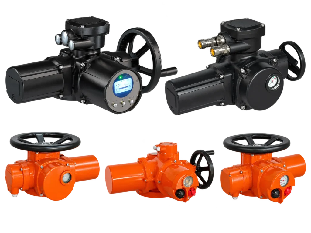
What Are the Main Types of Valve Actuators?
Industrial valve actuators can be classified according to their power source and operating mechanism. Electric and pneumatic designs are among the most common, while hydraulic actuators are used in applications requiring high force or specialized operation.
1. Electric Valve Actuator
An electric valve actuator uses an electric motor and reduction gearing to generate rotational torque or linear movement.
Electric models are commonly used where remote operation, position feedback, and integration with PLC or DCS systems are required.
Depending on the configuration, an electric actuator can support on-off control, proportional positioning, and intelligent communication.
Typical applications include motorized ball valves, electric butterfly valves, gate valves, and automated flow-control equipment.
Electric actuation is particularly useful where electrical power is available but a compressed-air network is not.
2. Pneumatic Valve Actuator
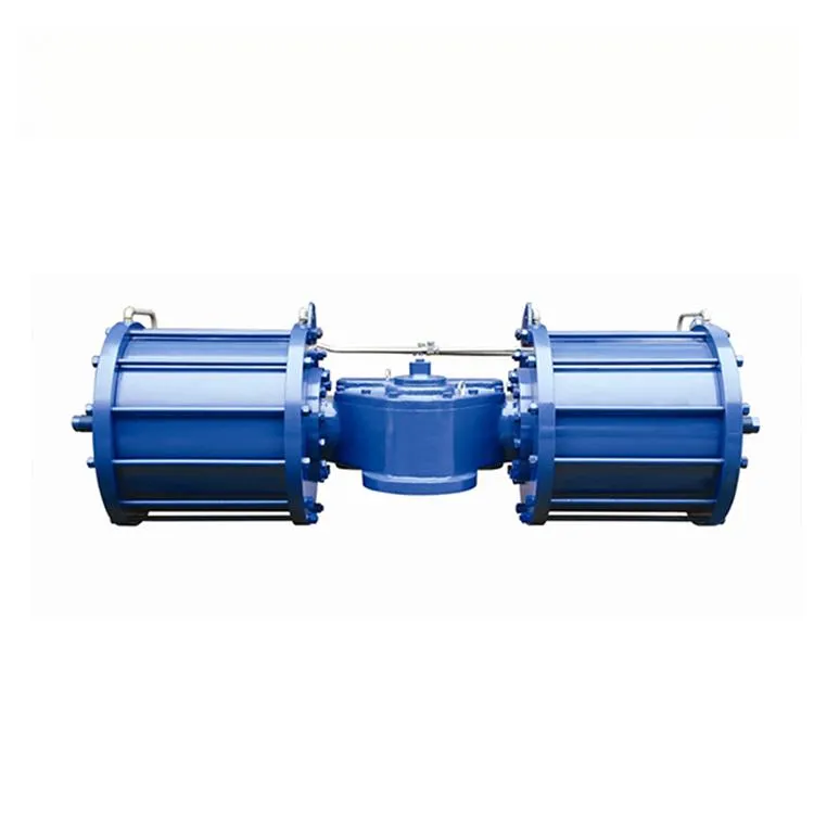
A pneumatic valve actuator converts compressed air pressure into mechanical movement. Depending on the design, it may use pistons, diaphragms, a rack-and-pinion mechanism, or a scotch-yoke mechanism.
Pneumatic actuators are commonly used for rapid switching, frequent operation, and industrial systems with reliable instrument-air supplies.
Two important configurations are double-acting and spring-return actuators.
Double-acting actuators use compressed air for movement in both directions. Spring-return actuators use stored spring force for one direction, allowing a defined response when the relevant air supply is removed.
Pneumatic valve actuators are widely used with ball valves, butterfly valves, plug valves, globe control valves, and suitable knife gate valves.
3. Hydraulic Valve Actuator
A hydraulic valve actuator uses pressurized hydraulic fluid to produce movement. Hydraulic systems can generate substantial force or torque and are used in selected high-load industrial applications.
They may be considered for large pipeline valves, specialized emergency shutdown systems, and other demanding operating duties.
However, hydraulic actuation requires suitable hydraulic power, pressure control, seals, and maintenance arrangements.
The need for hydraulic infrastructure makes it less attractive for some ordinary plant automation applications.
Quarter-Turn vs Multi-Turn vs Linear Valve Actuators
After choosing the power source, the next step is selecting the correct actuator movement. This is critical because different valve designs require different operating motions.
Quarter-Turn Valve Actuator
A quarter-turn actuator rotates the valve stem through approximately 90 degrees between its operating positions.
It is commonly used for ball valves, butterfly valves, and plug valves.
Quarter-turn valve actuator selection focuses on output torque, shaft connection, mounting interface, rotation direction, travel angle, and operating time.
ISO 5211 is commonly referenced for the attachment interface of part-turn valve actuators.
Multi-Turn Valve Actuator
A multi-turn actuator produces multiple rotations of its output shaft to move a valve through its full stroke.
It is frequently used for gate valves and other equipment requiring several stem rotations.
Multi-turn actuator selection must consider output torque, total number of turns, stem dimensions, output speed, and gearbox compatibility.
ISO 5210 is commonly used for multi-turn valve actuator attachments.
Linear Valve Actuator
A linear actuator generates a straight-line movement rather than directly rotating the valve shaft.
Typical applications include globe valves, certain gate valves, diaphragm valves, and knife gate valves.
Linear valve actuator sizing is based mainly on required thrust, travel distance, stroke speed, and the load generated by process pressure.
Some multi-turn actuator assemblies can also produce linear stem movement through a suitable screw or gearbox mechanism.
| Actuator Movement | Output | Typical Valve | Main Selection Factor |
|---|---|---|---|
| Quarter-Turn | Approximately 90° rotation | Ball, Butterfly, Plug | Torque and mounting interface |
| Multi-Turn | Multiple shaft rotations | Gate, selected Globe | Torque, turns, and output speed |
| Linear | Straight-line travel | Globe, Knife Gate, Diaphragm | Thrust and stroke length |
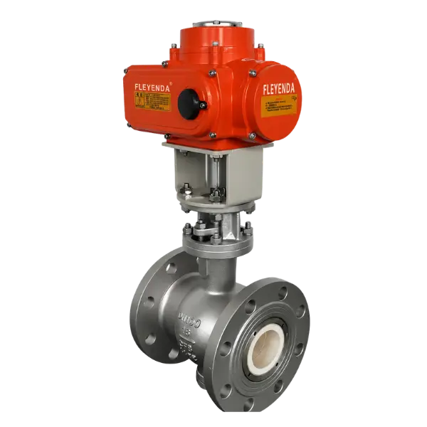
Valve Actuator Types Comparison
Each valve actuator technology has different advantages depending on the operating environment, control function, available utilities, and maintenance requirements.
| Factor | Electric | Pneumatic | Hydraulic |
|---|---|---|---|
| Power Source | Electricity | Compressed Air | Hydraulic Pressure |
| Typical Advantage | Remote control and positioning | Fast operation and spring-return options | High force and torque |
| Control | On/Off and Modulating | On/Off and Positioner Control | On/Off and Proportional |
| Required Utility | Electrical Supply | Instrument Air | Hydraulic Power |
| Failure Response | Depends on stored-energy design | Spring-return options available | Depends on hydraulic circuit |
| Maintenance Focus | Motor, gearbox, electronics | Air system, seals, pilot valve | Hydraulic seals, fluid, power unit |
The right choice depends on the application. A pneumatic actuator may be practical for frequent switching, while an electric actuator can simplify automation where compressed air is unavailable.
For large valves with demanding torque requirements, specialized pneumatic scotch-yoke or hydraulic arrangements may be evaluated.
How to Size a Valve Actuator: Torque and Thrust
Proper valve actuator sizing is essential for reliable operation. An undersized actuator may fail to complete its stroke, while excessive output without appropriate torque limitation can overload the valve stem or mounting components.
Valve Actuator Torque
Torque describes the turning force required to rotate a valve shaft. It is commonly expressed in Newton-meters (Nm).
For ball valves and butterfly valves, required operating torque changes throughout the stroke.
Engineers should consider breakaway torque, running torque, and seating or reseating torque.
Breakaway torque is the force required to begin movement from a stationary position. Running torque is the force required during travel, while seating torque is associated with reaching the final sealing position.
The valve actuator must provide sufficient torque at each relevant position under the specified pressure and temperature conditions.
Basic Torque Sizing Example
Suppose a valve manufacturer specifies a maximum required operating torque of 180 Nm under the intended process conditions.
If the engineering assessment establishes a 25% sizing margin for this particular application, the preliminary required actuator output becomes:
Required Actuator Torque = Valve Torque × Sizing Factor
180 Nm × 1.25 = 225 Nm
The selected actuator must therefore provide at least the required torque at the relevant operating position.
This is only a simplified example. Actual sizing should consider the complete valve torque curve, maximum allowable stem torque, service conditions, actuator characteristics, and the manufacturer’s recommended margin.
For pneumatic actuators, verify torque at minimum available air pressure and, for spring-return designs, throughout both the air and spring strokes. For electric actuators, verify rated output and torque-limitation settings. Do not size either type using a single catalogue number without checking the full duty.
Linear Valve Actuator Thrust
Linear valve actuators are generally sized by thrust rather than rotary torque. Thrust is usually expressed in Newtons (N) or kilonewtons (kN).
Required thrust depends on the valve design, pressure differential, effective pressure area, packing friction, seating load, and movement direction.
For globe control valves, actuator thrust should be checked at the critical pressure and travel positions.
The actuator stroke must also match the required valve travel to avoid incomplete closure or mechanical overtravel.
Key Valve Actuator Specifications to Check
Valve actuator selection requires checking several technical parameters beyond the output torque or thrust.
Power Supply and Control Signals
Electric valve actuators are available with different AC and DC power supply options, depending on the specific model.
Common configurations include AC110V, AC220V, AC380V, and DC24V. The selected voltage and frequency must match the installation.
On-off valve actuators generally use switching commands, while modulating configurations can support signals such as 4–20 mA or 0–10 V.
Some intelligent valve actuator models also support communication such as RS485/Modbus for integration with PLC, DCS, and SCADA systems.
IP67 and IP68 Protection
An actuator’s IP rating describes the level of protection provided by its enclosure against dust and water ingress.
IP67 provides protection for temporary immersion under specified test conditions. IP68 applies to immersion conditions agreed between the manufacturer and purchaser.
Therefore, an IP68 valve actuator should be selected according to the manufacturer’s stated immersion conditions rather than assuming unlimited underwater capability.
Cable glands, enclosure seals, and installation procedures also affect the maintained protection level.
Explosion-Proof Valve Actuator
Industrial facilities handling flammable gases or vapors may require a suitably certified explosion-protected valve actuator.
Available configurations may include protection concepts such as Ex d with appropriate gas groups and temperature classes.
For example, selected Fleyenda electric actuator models offer Ex d IIB T4 configurations. Other protection options depend on the specific product and certification.
The selected actuator and its electrical accessories must match the hazardous-area classification and applicable local requirements.
Operating Time and Duty Cycle
Actuator operating time should be selected according to the required valve response and process safety conditions.
A very fast actuator is not always desirable, especially in liquid pipelines where rapid valve closure can contribute to pressure surge.
Duty cycle is particularly important for modulating valves that reposition frequently. An on-off actuator designed for occasional switching should not automatically be used for continuous proportional control.
Mounting and Interface Standards
The connection between a valve and actuator must provide suitable mechanical alignment and transmit the required torque or thrust.
ISO 5211 is commonly applied to part-turn actuator attachments, while ISO 5210 covers multi-turn actuator attachments.
The mounting flange, shaft dimensions, coupling geometry, bolt pattern, and allowable loads should all be verified.
A compatible mounting pattern alone does not guarantee that an actuator has sufficient output or that the valve stem can tolerate the actuator’s maximum torque.
Fleyenda Valve Actuator Series
Fleyenda offers different valve actuator configurations for quarter-turn and multi-turn applications, industrial flow control, and high-torque valve automation.
The following four series illustrate common selection options for different operating duties.
A quarter-turn electric actuator designed for ball valves, butterfly valves, and other compatible rotary applications.
On-off, modulating, and intelligent configurations are available, with selected IP68 and explosion-proof options for industrial environments.
A quarter-turn electric actuator series for industrial valve automation, including selected regulating and intelligent control configurations.
Suitable for projects requiring controlled rotation, feedback, and specified environmental or hazardous-area protection.
A multi-turn electric actuator series designed for valves requiring multiple shaft rotations, including selected gate and globe valve applications.
Available control configurations include on-off, regulating, and intelligent operation, depending on the specified model.
A pneumatic scotch-yoke actuator series designed for high-torque quarter-turn applications.
Double-acting and spring-return arrangements are available for suitable large ball valves, butterfly valves, and other industrial rotary valves.
How to Choose the Right Valve Actuator
A reliable valve actuator selection process starts with the valve and process conditions. The actuator should be selected only after the required operating motion and load have been defined.
Identify the Valve Type
Determine whether the application uses a ball valve, butterfly valve, gate valve, globe valve, knife gate valve, or another design.
Establish whether the required movement is quarter-turn, multi-turn, or linear.
Determine Torque or Thrust
Request the valve manufacturer’s operating torque or thrust data for the actual service conditions.
Consider pressure differential, seat construction, temperature, valve size, and any appropriate sizing margin.
Choose the Power Source
Confirm the available electrical power, compressed air, or hydraulic supply.
Consider the operating frequency, required response speed, installation location, and maintenance infrastructure.
Specify the Control Function
Define whether the valve requires simple open-close movement or modulating positioning.
Confirm the required signal, such as dry contact, 4–20 mA, 0–10 V, or an applicable digital protocol.
Confirm Environmental Protection
Check ambient temperature, humidity, corrosion exposure, dust, water ingress, and hazardous-area classification.
Select the appropriate IP rating and certified explosion-protection option where required.
Verify Mounting and Safety Requirements
Confirm mounting standard, coupling dimensions, output shaft geometry, travel limit, maximum permissible load, and failure position.
The complete valve-and-actuator assembly should be checked for mechanical compatibility and the intended control sequence.
Valve Actuator RFQ Checklist
- Valve type, size, and mounting standard
- Required operating torque or thrust
- Maximum allowable valve stem torque
- Quarter-turn, multi-turn, or linear motion
- Power voltage or pneumatic air-supply pressure
- Operating time and cycle frequency
- On-off or modulating control
- Control signal and position feedback
- IP rating and explosion-proof requirements
- Fail-open, fail-closed, or fail-in-place requirement
- Ambient conditions and project quantity
Industrial Applications of Valve Actuators
Different industries require different valve actuator configurations because operating environments and process requirements vary.
Water and Wastewater Treatment
Electric valve actuators are commonly used for remote isolation and automated control of water pipelines, filter systems, and pump stations.
Pneumatic actuators are also suitable for repeated switching where reliable instrument air is available.
Petrol ve Doğal Gaz
Oil and gas applications may require high-torque actuators, fail-safe operation, and appropriately certified hazardous-area equipment.
Pneumatic scotch-yoke actuators can be considered for demanding rotary valve duties, while electric multi-turn actuators are suitable for selected gate valve applications.
Kimyasal İşleme
Chemical facilities use valve actuators to automate compatible isolation and control valves in transfer lines, reactors, and dosing systems.
Corrosion exposure, process safety requirements, instrument reliability, and explosion protection influence the selection.
Metallurgy and Heavy Industry
Valve actuators are used in cooling water, process gas, industrial utilities, and automated production systems.
High ambient temperatures, dust, vibration, and frequent cycling can require more demanding actuator protection and duty ratings.
Pump Systems
Motorized ball valves, butterfly valves, and other actuated valves support pump isolation, switching, and flow-routing functions.
The actuator’s operating time must be compatible with the pump sequence and system hydraulic conditions to help prevent pressure surges.
Common Valve Actuator Selection Mistakes
Many actuator problems begin with incomplete engineering specifications rather than equipment defects.
| Common Mistake | Possible Result | Better Approach |
|---|---|---|
| Selecting by DN only | Insufficient torque | Use valve-specific torque data |
| Ignoring minimum air pressure | Incomplete pneumatic stroke | Size at minimum available pressure |
| Incorrect actuator motion | Mechanical incompatibility | Verify quarter-turn, multi-turn, or linear travel |
| Using on-off models for continuous modulation | Premature wear or poor positioning | Specify suitable modulating duty |
| Ignoring valve stem torque limits | Mechanical overload | Verify maximum permissible stem torque |
| Assuming all IP68 models are identical | Inadequate water protection | Verify actual certified enclosure conditions |
| Ignoring failure position | Incorrect shutdown behavior | Specify fail-safe function in advance |
Request Valve Actuator Selection Support
Choosing the correct valve actuator requires a detailed understanding of the valve’s mechanical load, process conditions, mounting requirements, and operating function.
Fleyenda provides electric and pneumatic actuator series and integrated valve automation solutions for industrial projects.
Whether you need a quarter-turn electric actuator, a multi-turn gate valve actuator, or a high-torque pneumatic actuator, sharing the technical requirements will help identify a suitable configuration.
Need a Valve Actuator for Your Project?
Send the valve type, operating torque or thrust, control requirements, power supply, and installation conditions to Fleyenda for technical selection and quotation.
Valve Actuator Frequently Asked Questions
What is a valve actuator?
A valve actuator is a device that automatically moves a valve to open, close, or regulate fluid flow. It converts electrical, pneumatic, or hydraulic power into mechanical motion.
What are the main types of valve actuators?
The main power types are electric, pneumatic, and hydraulic. Actuators can also be classified by movement as quarter-turn, multi-turn, or linear.
How do I choose the correct valve actuator size?
Determine the valve’s maximum required torque or thrust under actual operating conditions. Then select an actuator that provides sufficient output throughout the stroke while respecting valve mechanical limits.
What is the difference between quarter-turn and multi-turn actuators?
Quarter-turn actuators commonly rotate a valve through approximately 90 degrees. Multi-turn actuators produce multiple shaft rotations and are commonly used with gate valves and similar equipment.
What does valve actuator torque mean?
Torque is the rotational force generated by the actuator. It must be sufficient to overcome the valve’s breakaway, running, and seating torque under the specified operating conditions.
What is an IP68 valve actuator?
An IP68 valve actuator has an enclosure designed for dust-tight protection and immersion under conditions specified by the manufacturer. The exact water-depth and exposure limits must be confirmed for the selected model.
Can a valve actuator support 4–20 mA control?
Yes. Selected electric modulating actuators and pneumatic actuators equipped with suitable positioners can respond to 4–20 mA commands for proportional positioning.
What is an explosion-proof valve actuator?
An explosion-protected actuator uses a certified protection design suitable for specified hazardous locations. Its gas group, temperature class, equipment protection level, and certification must match the installation requirements.
Can one actuator fit different valve brands?
Sometimes. Mounting standards such as ISO 5211 and ISO 5210 support interface compatibility, but the torque or thrust, coupling, stem dimensions, travel, and mechanical limits must still be verified.
What information should I provide when buying a valve actuator?
Provide the valve type, nominal size, required torque or thrust, mounting dimensions, power supply, control signal, operating time, duty cycle, ambient conditions, IP rating, and failure-position requirements.
Conclusion: Selecting the Right Valve Actuator
The correct valve actuator must match the valve’s movement, operating load, control requirements, and industrial environment.
Quarter-turn actuators are commonly used for ball and butterfly valves, multi-turn actuators for gate valves, and linear actuators for globe and other linear-stroke applications.
Electric actuators offer convenient remote control and integration with industrial automation systems. Pneumatic actuators are useful for fast operation and suitable spring-return functions, while hydraulic systems serve selected high-force applications.
For reliable operation, engineers should verify torque or thrust, control signals, duty cycle, mounting compatibility, environmental protection, and the required failure response before choosing the final valve actuator configuration.