


Pnömatik Aktüatörlü Vana Seçim Kılavuzu
Selecting a pneumatic actuator valve is not simply a matter of matching an actuator to the nominal size of a valve. A reliable automated valve package depends on the interaction between valve torque, actuator output, air-supply pressure, fail-safe requirements, process pressure, operating temperature, control accessories and the actual duty of the system.
Two pneumatic actuator valves with the same nominal diameter may require very different actuator sizes. A soft-seated ball valve handling clean water at moderate pressure will not impose the same torque demand as a large trunnion-mounted ball valve operating under high differential pressure. Likewise, a valve used only for open-close isolation has different control requirements from a V-port ball valve used for continuous flow modulation.
For water treatment, pump systems, oil and gas, chemical processing and industrial pipelines, actuator selection should therefore begin with the process conditions and valve mechanics. Only after these are defined should the pneumatic actuator, solenoid valve, positioner, limit switch and fail-safe configuration be finalized.
A pneumatic actuator valve should be selected as one complete valve-and-actuator assembly. Valve torque and actuator torque must be evaluated at the minimum available air pressure and under the most demanding operating condition.
Where Should Pneumatic Actuator Valve Selection Start?
Pneumatic actuator valve selection should start with the process, not with the actuator catalogue. The first step is to define what the valve must do, what medium passes through it and what mechanical load the process will create.
Engineers should establish the normal operating pressure, maximum differential pressure, minimum and maximum temperature, valve size, pipe connection and required shut-off performance. The medium should also be evaluated for corrosion, solids, viscosity and the possibility of deposits forming around the closure element.
Once the valve body and internal design are defined, the required operating torque or thrust can be determined. The pneumatic actuator is then selected to provide sufficient output at the actual minimum air pressure available at the installation.
Control philosophy comes next. The system may require simple on-off operation, spring-return emergency action, proportional positioning or feedback to a PLC or DCS.

Define the Valve Function Before Selecting the Actuator
The same pneumatic actuator technology can operate ball valves, butterfly valves, plug valves and other quarter-turn devices, while pneumatic cylinders can also be used for linear valves. However, actuator sizing and control configuration depend heavily on the actual valve function.
An isolation valve normally spends most of its life fully open or fully closed. Its actuator therefore needs reliable breakaway torque and secure end positioning rather than continuous modulation capability.
A control valve behaves differently. A pneumatic actuator valve used for throttling may move hundreds or thousands of times while holding intermediate positions. Positioner accuracy, actuator stiffness, hysteresis and the valve’s inherent flow characteristic become more important.
Three-way valves introduce another requirement because the actuator may need to move the closure element between specific flow-routing positions instead of simply opening or closing one flow path.
Double-Acting vs Spring-Return Pneumatic Actuator
One of the first actuator decisions is whether the pneumatic actuator valve should use a double-acting actuator or a spring-return actuator.
Double-Acting Pneumatic Actuator
A double-acting actuator uses compressed air to move the actuator in both directions. Air is supplied alternately to opposite sides of the piston mechanism to open and close the valve.
Because both strokes are powered pneumatically, double-acting actuators can provide a compact solution when no automatic safety position is required after loss of air supply.
Spring-Return Pneumatic Actuator
A spring-return actuator uses compressed air for movement in one direction and stored spring energy for the return stroke. When air pressure is removed, the spring drives the valve toward a predetermined safety position.
This arrangement is frequently used where the valve must automatically move to a fail-open or fail-close position after loss of instrument air or electrical power to the solenoid valve.
| Selection Factor | Double Acting | Spring Return |
|---|---|---|
| Opening force | Compressed air | Air or spring depending on configuration |
| Closing force | Compressed air | Spring or air depending on configuration |
| Fail-safe action | Requires additional system strategy | Can provide defined fail position |
| Actuator size | Often more compact for the same valve torque | May require larger actuator because spring torque must be considered |
| Typical duty | General automation and frequent cycling | Applications requiring automatic safety return |
Fail-Open, Fail-Close or Fail-in-Place?
Fail-safe selection should be based on the consequence of losing air or control power. There is no universally correct safety position for a pneumatic actuator valve.
A fuel supply valve may need to close automatically. A cooling-water valve may need to remain open. A process diversion valve may require a specific position determined by the piping and process safety analysis.
For spring-return actuators, the actuator orientation and spring configuration determine whether the valve moves to fail-open or fail-close.
If fail-in-place behavior is required, the pneumatic circuit may need additional components such as lock-up valves or air reservoirs. The valve manufacturer and control-system designer should therefore agree on the required failure philosophy before actuator sizing is finalized.
Air Supply Pressure Is a Design Parameter
Pneumatic actuator output changes directly with supply pressure. An actuator that produces sufficient torque at 6 bar may not provide the same safety margin if the actual plant air pressure falls to 4 bar.
This is why actuator sizing must be based on minimum guaranteed air pressure rather than the normal compressor discharge pressure.
Pressure losses through filters, regulators, tubing, solenoid valves and long pneumatic lines should also be considered. The pressure reaching the actuator during a fast stroke can be lower than the pressure measured at the main air header.
Fleyenda’s pneumatic actuator configurations are specified around an air-supply range of approximately 3–8 bar, depending on the selected actuator and application. Final actuator sizing should still use the minimum confirmed pressure available at the valve location.
How to Size Pneumatic Actuator Torque
Pneumatic actuator sizing should begin with the valve torque curve. Quarter-turn valves generally do not require the same torque throughout the complete 90-degree stroke.
Ball valves often require relatively high breakaway torque when movement begins because the ball must overcome seat friction. Running torque may then decrease through the middle of the stroke before increasing again as the ball reaches its final seated position.
Differential pressure, temperature, seat material, valve age, deposits and long periods without cycling can increase the required torque.
The actuator should therefore be checked at all relevant angular positions, not simply against one catalogue torque number.
Practical sizing principle: available actuator torque at minimum air pressure must remain above the maximum required valve torque throughout the entire stroke, with an appropriate engineering margin for the service.
Applying a fixed safety factor without understanding the valve torque curve can still produce incorrect sizing. Severe service, metal seats, high differential pressure or infrequent cycling may require a larger margin than clean-water service.
Pneumatic Actuator Ball Valve Selection
A pneumatic actuator ball valve is widely used when rapid quarter-turn isolation, reliable shut-off and automation are required.
For clean liquids and gases, soft-seated ball valves can provide low operating torque and high shut-off performance. In high-temperature or abrasive conditions, PEEK or metal seats may be more appropriate, although the resulting valve torque can be significantly higher.
Port design also matters. Full-port ball valves minimize flow restriction, while reduced-port designs may reduce size and cost where additional pressure loss is acceptable.
Large-diameter and high-pressure ball valves require further attention to ball support. Trunnion-mounted designs mechanically support the ball and are commonly used when pressure-induced seat loading becomes significant.
When Should You Use a Pneumatic V-Port Ball Valve?
A standard round-port ball valve is primarily intended for isolation. Although it can be placed at an intermediate position, its flow characteristic is usually not ideal for precise throttling.
A pneumatic V-port ball valve uses a specially shaped opening in the ball to produce a more predictable relationship between valve position and flow area.
This makes the design more suitable for applications where the pneumatic actuator valve must regulate flow instead of simply opening and closing.
The actuator is normally paired with a pneumatic positioner. A control signal such as 4–20 mA is converted into the air-pressure adjustment required to move the valve to the commanded position.
V-port valves can be useful for water, steam, air, gas, process liquids and selected slurry services, provided the seat, body and trim materials are appropriate for the medium.
When Should You Use a Pneumatic Trunnion Mounted Ball Valve?
As ball valve size and differential pressure increase, the hydraulic load acting on the ball can become substantial. In these conditions, a trunnion-mounted design provides mechanical support at the top and bottom of the ball.
The supported ball arrangement helps control seat loading and makes the design suitable for large pipelines and demanding pressure classes.
A pneumatic trunnion ball valve is therefore commonly considered for oil and gas pipelines, compressor and pump stations, high-pressure utilities and other large industrial isolation duties.
These valves often require larger pneumatic actuators, particularly when metal seats, high differential pressure or emergency shutdown functions are involved.
Pneumatic Actuator Valve Product Options
The correct product depends on whether the process requires accurate throttling or heavy-duty isolation. The following two configurations illustrate two very different pneumatic actuator valve applications.

FAT-VQ-F combines a V-port ball valve with a pneumatic actuator for proportional flow regulation. The V-shaped ball makes it more suitable for throttling applications where a conventional round-port ball valve cannot provide the required control characteristic.
DN15–DN200
-20 °C ile +180 °C arası
CF8 / CF8M stainless steel
ANSI / DIN / JIS flanged
Double acting or spring return
Positioner and 4–20 mA options
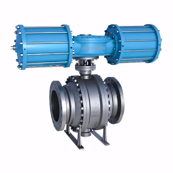
FAW-Q combines a trunnion-supported ball valve with an AW pneumatic actuator for large-diameter and high-pressure isolation. The supported ball structure is designed for applications where pressure loading and required operating torque are significantly higher than in smaller general-purpose ball valves.
DN50–DN600
Class 150–2500 / PN16–PN420
-29°C to +425°C
Carbon steel / stainless steel
AW double acting or spring return
Oil, gas, water, steam and process media
Solenoid Valves, Positioners and Limit Switches
The pneumatic actuator is only one part of an automated valve package. Control accessories determine how the valve receives commands, regulates position and reports its status to the plant control system.
Solenoid Valf
A solenoid valve directs compressed air to the actuator in response to an electrical signal. It is commonly used for on-off pneumatic actuator valve applications.
The solenoid configuration must match the actuator type. Double-acting and spring-return actuators may require different pneumatic circuits.
Pneumatic Positioner
A positioner is used when the valve needs to move accurately to intermediate positions. It compares the command signal with actual valve position and adjusts actuator pressure until the requested position is reached.
Positioners are particularly important for pneumatic V-port ball valves and other throttling applications.
Sınır Anahtarı
A limit switch provides electrical confirmation of valve position. PLC or DCS systems can use this feedback to verify that the valve has completed the required stroke before the next process step begins.
Filter Regulator
An air filter regulator helps remove contamination and maintain stable actuator supply pressure. In many industrial systems it is one of the most important accessories for long-term actuator reliability.
Do Not Ignore Instrument Air Quality
Reliable pneumatic actuator valve operation depends on clean and sufficiently dry compressed air.
Water, rust, oil contamination and solid particles can damage actuator seals, block small pneumatic passages or cause positioners and solenoid valves to operate unpredictably.
This becomes especially important for modulating control because pneumatic positioners use much smaller internal passages than a basic actuator cylinder.
Air preparation should therefore be considered part of actuator selection rather than an unrelated utility-system issue.
Valve Pressure and Temperature Must Be Checked Separately
Pneumatic actuator pressure rating and valve process-pressure rating describe two completely different systems.
The valve body contains the process medium and must be rated for the pipeline pressure and temperature. The pneumatic actuator receives instrument air, normally at a much lower pressure.
Process temperature can also affect actuator sizing indirectly. Elevated temperature may increase seat friction, change seal behavior and require high-temperature mounting arrangements to protect actuator components from heat.
For steam, thermal oil and other high-temperature media, the temperature limits of the body, seats, stem packing and actuator mounting assembly should all be checked.
Valve Body, Seat and Seal Material Selection
Material selection should reflect the process medium rather than simply choosing stainless steel by default.
Carbon steel is widely used in oil and gas and general industrial pipelines. Stainless steels such as 304, 316 and CF8M can provide improved corrosion resistance for water, chemical and process applications.
Seat material has an equally important effect on pneumatic actuator valve performance because it influences sealing, temperature capability, wear resistance and operating torque.
PTFE-based seats are suitable for many clean-fluid applications. PEEK can provide improved mechanical and temperature capability in more demanding service. Metal seats are considered for high-temperature, abrasive or severe process conditions.
Changing from a soft seat to a metal seat can significantly change the torque requirement, so the existing actuator should never be assumed suitable without recalculation.
Operating Speed and Cycle Frequency
Pneumatic actuators are capable of relatively fast operation, but the shortest possible stroke time is not always desirable.
In liquid systems, very rapid valve closure can contribute to pressure surge or water hammer. In large ball valves, rapid acceleration and deceleration can also increase mechanical stress on the valve stem, coupling and actuator.
On the other hand, emergency isolation or high-speed production equipment may require fast valve response.
The required opening and closing time should therefore be specified from the process requirement. Flow-control valves should also be evaluated by duty cycle because frequent modulation places much more demand on actuator seals, positioners and air consumption than occasional isolation.
Environmental and Hazardous-Area Requirements
The pneumatic mechanism itself does not remove the need to evaluate environmental and electrical requirements.
Solenoid valves, positioners and limit-switch boxes may contain electrical components and therefore require suitable ingress protection for outdoor, dusty or wet industrial environments.
In oil and gas, petrochemical and chemical plants, these accessories may also require explosion-proof or intrinsically safe configurations compatible with the site’s hazardous-area classification.
The required certification, gas group, temperature class and protection concept should be specified during procurement rather than after the valve has arrived on site.
Pneumatic Actuator Valve Applications
Su Arıtma
Pneumatic actuator valves can automate filter systems, treatment skids, chemical dosing systems, tank transfer and process-water isolation. Clean instrument air and corrosion-resistant valve materials are often important selection factors.
Pump Systems and Pump Skids
Pneumatic ball valves are frequently integrated with pump sequencing. The valve opening and closing signal can be coordinated with pump start and stop commands, while position feedback confirms that the valve has reached the required state.
Petrol ve Doğal Gaz
High-pressure oil and gas pipelines often require large pneumatic trunnion-mounted ball valves. Actuator torque, fail-safe action, fire-safe valve design and hazardous-area accessories become major procurement considerations.
Kimyasal İşleme
Chemical service requires careful verification of body, ball, stem, seat and seal compatibility. Spring-return actuators may be used where the process requires a defined position after loss of control air.
Metalurji
Metallurgical plants use pneumatic actuator valves in cooling water, utility gas, compressed air and process systems. Dust, heat and high cycle frequency can influence actuator and accessory selection.
Pneumatic Actuator Valve Installation and Commissioning
Before installation, verify that the actuator orientation, valve flow direction where applicable, fail position and accessory configuration match the approved drawings.
The piping should be aligned so that the valve body is not used to correct pipe misalignment. Large valve-and-actuator assemblies may require independent structural support.
Pneumatic tubing should be sized to provide sufficient airflow for the required stroke time. Long or undersized tubing can slow actuator response even when the main air header pressure is adequate.
During commissioning, cycle the valve several times while checking open and closed feedback, air leakage, actuator movement and final valve position.
For modulating valves, calibrate the positioner and verify valve travel against the command signal across the complete operating range.
Pneumatic Actuator Valve Maintenance
Pneumatic actuator valve maintenance should focus on both the valve and the air-control system.
Regular inspection should include actuator air leakage, tubing condition, solenoid operation, filter condition, positioner response, limit-switch accuracy and the mechanical coupling between actuator and valve.
Increasing operating time or inconsistent travel can indicate reduced air pressure, contamination, seal wear or rising valve torque.
The valve itself should also be inspected for seat leakage, stem leakage and changes in operating torque. A developing valve problem can initially appear to be an actuator problem because both affect stroke performance.
Common Pneumatic Actuator Valve Selection Mistakes
One common mistake is selecting the actuator only from valve diameter. Valve torque depends on much more than DN and can change substantially with pressure, seat material and process condition.
Another mistake is sizing the actuator at normal plant air pressure rather than minimum available pressure.
Fail-safe requirements are also sometimes considered too late. Changing a double-acting actuator to spring return can significantly change actuator size and available torque.
For control applications, selecting a standard on-off ball valve instead of a proper V-port or control valve can produce unstable flow regulation.
Finally, control accessories should not be treated as generic components. Solenoid flow capacity, positioner type, electrical signal, explosion protection and limit-switch configuration all affect the performance of the complete pneumatic actuator valve assembly.
What to Include in a Pneumatic Actuator Valve RFQ
A useful RFQ should provide the manufacturer with enough information to size both the valve and pneumatic actuator correctly.
Start with the medium, nominal size, maximum pressure, maximum differential pressure, minimum and maximum temperature, body material, seat material and required connection standard.
Then define the valve function: isolation, emergency shutdown, diversion or throttling.
For the pneumatic actuator, specify minimum and normal air-supply pressure, double-acting or spring-return configuration, required fail position and desired opening or closing time.
Control-system information should include solenoid voltage, positioner input signal, position feedback, PLC or DCS requirements and any hazardous-area certification.
A request such as “pneumatic actuator valve DN100” is not enough for correct actuator sizing. Minimum air pressure, differential pressure, valve torque, fail action and control function are essential engineering inputs.
Sık Sorulan Sorular
How do I select a pneumatic actuator valve?
Start with the process medium, valve size, pressure, differential pressure, temperature and required valve function. Then determine valve torque and select an actuator that provides sufficient torque at the minimum available air pressure.
How much air pressure does a pneumatic actuator need?
Required pressure depends on actuator size and valve torque. Industrial pneumatic actuators commonly operate within a defined compressed-air range, but sizing should always use the minimum guaranteed pressure available at the actuator.
What is the difference between double-acting and spring-return actuators?
A double-acting actuator uses compressed air in both directions. A spring-return actuator uses spring energy for one direction, allowing the valve to move toward a defined position after loss of air.
How much safety margin should pneumatic actuator torque have?
The appropriate margin depends on valve design and operating conditions. High pressure, metal seats, dirty media or infrequent operation can justify a larger allowance. The final sizing should use the valve manufacturer’s torque data rather than a universal percentage alone.
When should I choose a pneumatic V-port ball valve?
A V-port ball valve is appropriate when proportional flow regulation is required. Its shaped opening provides a more controlled relationship between valve position and flow area than a conventional round-port ball valve.
When is a pneumatic trunnion ball valve required?
Trunnion-mounted ball valves are commonly selected for larger diameters, high pressure and demanding pipeline isolation where the ball requires mechanical support and controlled seat loading.
Does a pneumatic actuator valve need a positioner?
Not always. Simple on-off valves can normally operate with a solenoid valve and position feedback. A positioner is generally required when the valve must accurately control intermediate positions.
What happens if instrument air fails?
The result depends on actuator and pneumatic-circuit design. A spring-return actuator can drive the valve toward a predefined fail-open or fail-close position when air pressure is lost.
Can a pneumatic actuator valve connect to a PLC or DCS?
Yes. Solenoid valves, limit switches and positioners can provide command and feedback interfaces for automated industrial control systems.
Sonuç
Correct pneumatic actuator valve selection requires more than choosing an actuator according to valve size. Valve torque, minimum air-supply pressure, differential pressure, operating temperature and process medium all influence actuator requirements.
The choice between double-acting and spring-return operation should be based on the required failure behavior, while positioners, solenoid valves and limit switches should be selected according to the control philosophy.
Valve construction is equally important. A pneumatic V-port ball valve can provide accurate proportional flow control, while an AW trunnion-mounted ball valve is better suited to large-diameter and high-pressure isolation.
For water treatment, pump systems, oil and gas, chemical processing and metallurgy, the most reliable approach is to treat the valve, actuator, air supply and control accessories as one engineered package.
When these factors are evaluated together, a pneumatic actuator valve can provide fast, repeatable and reliable automated operation throughout the intended service life.