


INDUSTRIAL ELECTRIC VALVE CONTROL GUIDE
Modulating vs On-Off Control: 4-20mA Electric Actuator Guide
A 4-20mA electric actuator provides an analog control interface for positioning automated valves in industrial process systems. Understanding the difference between on-off and modulating control is essential when selecting an electric actuator for water flow control, pipeline automation and process regulation. This guide explains how 4-20mA control works, compares actuator operating modes, reviews technical specifications and applicable industry standards, and helps engineers select the right electric valve configuration.
FLEYENDA ELECTRIC VALVE RANGE
Electric Actuated Ball Valve Products
Explore Fleyenda electric ball valve configurations for industrial automation, water treatment and process control.
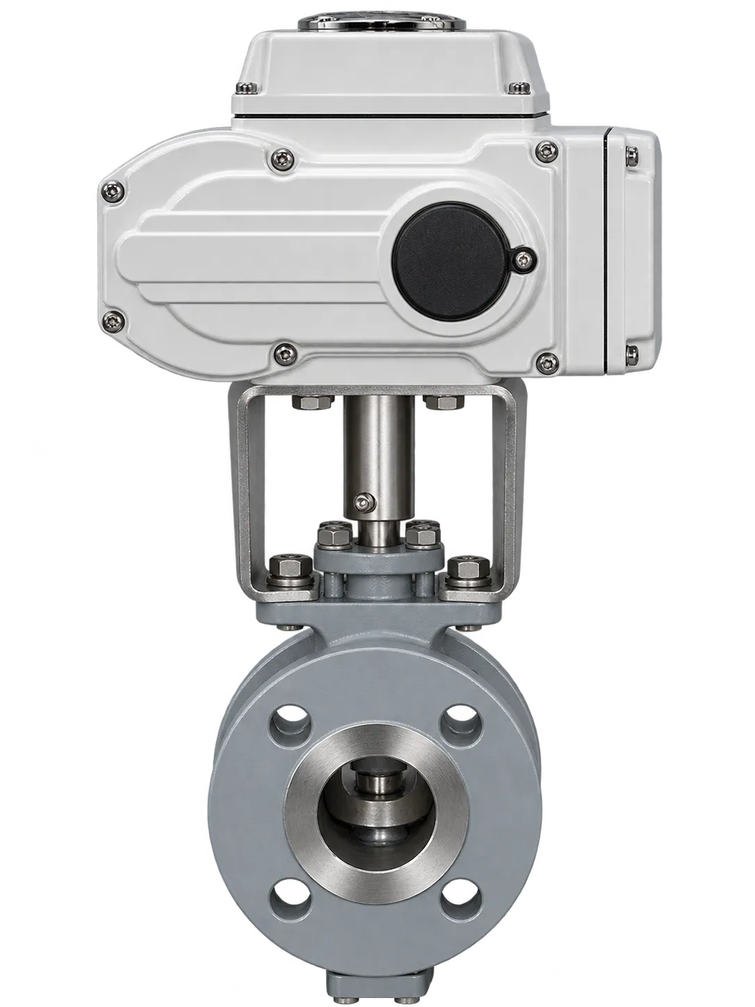
FLE-VQ-F SERIES
Electric V-Port Ball Valve
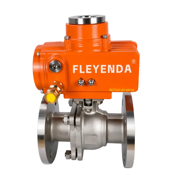
FLE-Q-F SERIES
Electric 2-Way Flanged Ball Valve
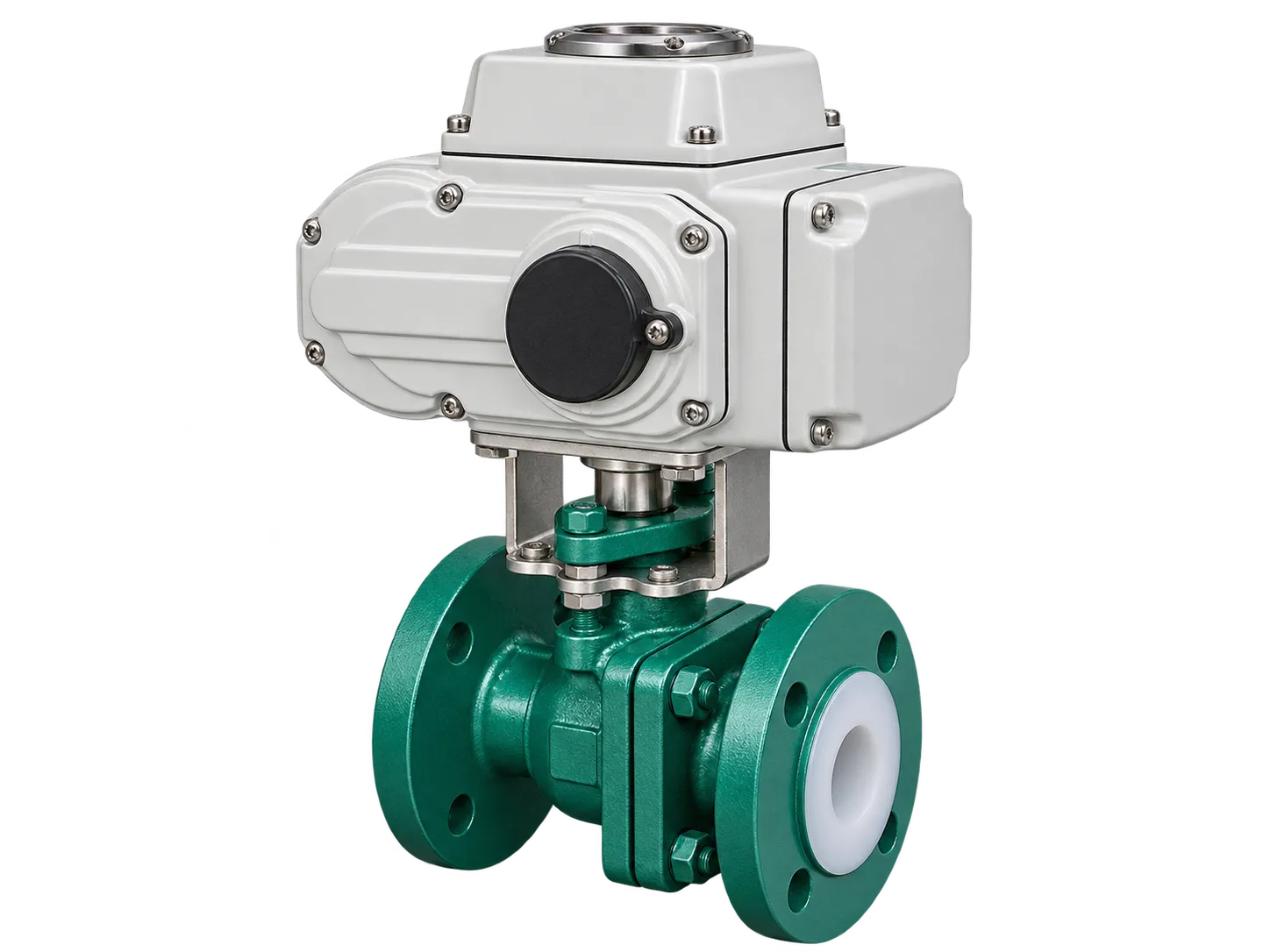
FLE-Q-F LINED SERIES
PTFE/PFA-Lined Electric Ball Valve
What Is the Difference Between Modulating and On-Off Control?
The main difference is how the electric actuator responds to the control command. An on-off electric actuator moves the valve between fully open and fully closed positions. A modulating electric actuator receives an analog signal, such as 4-20mA, and adjusts the valve position according to the input value.
For applications that only require pipeline isolation, on-off control is generally sufficient. For applications that require continuous adjustment of water flow, pressure, temperature or process conditions, a compatible modulating actuator and suitable control valve are required.
Fully Open / Fully Closed
Suitable for automatic isolation, equipment switching and pipeline shutoff.
0-100% Position Adjustment
Suitable for proportional flow regulation and automated process control.
On-Off Electric Actuator vs Modulating Electric Actuator
Both actuator configurations automate valve operation, but their control logic, signal requirements and operating purposes are different. Selecting the correct type is important for avoiding unstable control, unnecessary actuator costs and unsuitable valve operation.
| Comparison | On-Off Actuator | Modulating Actuator |
|---|---|---|
| Operating Mode | Open or closed | Intermediate positioning |
| Control Input | Open/close switching signal | 4-20mA or 0-10V |
| Position Control | Two-position operation | Proportional position control |
| Feedback | Open/close limit contacts | Position feedback, depending on configuration |
| Typical Application | Pipeline isolation and switching | Flow, pressure and temperature regulation |
| Control System | Relay, PLC or remote switch | PLC, DCS or analog controller |
| Valve Compatibility | Compatible ball, butterfly and gate valves | Suitable control ball, V-port, butterfly or globe valves |
Installing a modulating actuator does not automatically make every valve suitable for precise flow regulation. Valve flow characteristics, sizing, rangeability, pressure drop and actuator positioning performance must also be considered.
How Does a 4-20mA Electric Actuator Work?
A 4-20mA electric actuator converts an analog electrical command into mechanical valve movement. The signal normally represents a requested valve position or control demand. The actuator interprets the input and drives the valve toward the corresponding position.
In a typical industrial water flow control system, a PLC or DCS receives information from flow, pressure or level transmitters. The controller compares the measured process value with the required setpoint and sends an updated 4-20mA command to the modulating actuator.
Process Measurement
A flow, pressure or level transmitter measures the actual operating condition.
PLC / DCS Controller
The controller compares the process measurement with the target setpoint.
4-20mA Control Signal
An analog output sends the required position command to the electric actuator.
Electric Actuator Movement
The actuator positions the valve according to the configured input range.
Process Adjustment
The resulting valve opening changes the flow characteristics of the pipeline.
Understanding the 4mA and 20mA Signals
In a common 0-100% position mapping, 4mA represents the configured minimum position and 20mA represents the configured maximum position. Intermediate signals correspond to intermediate setpoints.
This table assumes a linear 4-20mA input mapped to a 0-100% actuator travel range. Actual valve flow is not necessarily linear with the electrical signal. The final relationship depends on the valve’s inherent flow characteristic, installed conditions and control configuration.
4-20mA Water Flow Control Valve: Technical Specifications and Industry Standards
When specifying a 4-20mA water flow control valve, engineers need to evaluate both the valve body and the electric actuator. The valve determines the flow capacity, pressure rating, sealing performance and material compatibility, while the actuator determines the available control modes, positioning capability and automation interface.
A complete technical specification should include the following information before equipment procurement.
Typical Technical Specifications
| Parameter | Typical Options | Selection Consideration |
|---|---|---|
| Valve Type | Ball, V-port ball, butterfly, globe | Isolation or regulating duty |
| Nominal Size | DN15 and above, according to series | Required flow and pipe dimensions |
| Pressure Rating | PN10, PN16, PN25, PN40 and selected classes | Design pressure and differential pressure |
| Body Materials | WCB, SS304, SS316 and other compatible materials | Water quality and corrosion conditions |
| Seat Materials | PTFE, RPTFE, EPDM and other compatible materials | Temperature, media and sealing requirements |
| Control Signal | 4-20mA, 0-10V, on/off | PLC / DCS compatibility |
| Position Feedback | 4-20mA, 0-10V or limit contacts | Monitoring and control requirements |
| Power Supply | DC24V, AC110V, AC220V, AC380V | Available electrical infrastructure |
| Protection | IP65, IP67, IP68 options | Indoor, outdoor and wet environments |
| Communication | Modbus and selected fieldbus options | Automation system requirements |
Applicable Industry Standards
Industry standards should be selected according to valve construction, actuator, pressure class, installation and project requirements. The following standards are relevant reference points for engineering specifications.
| Standard | Scope | Application |
|---|---|---|
| IEC 60381-1 | Analog direct-current signals for process control systems | 4-20mA signal interface |
| IEC 60529 | Degrees of protection provided by enclosures | IP protection rating |
| ISO 5211 | Part-turn actuator attachment | Actuator mounting interface |
| ASME B16.34 | Valve pressure-temperature ratings and construction requirements | Applicable industrial valve bodies |
| ASME B16.5 | Pipe flanges and flanged fittings | Flanged valve connections |
| API 598 | Valve inspection and testing | Applicable valve testing requirements |
| IEC 60534 | Industrial-process control valves | Applicable control-valve sizing and performance requirements |
These are reference standards, not a blanket certification statement for every Fleyenda product. The applicable edition, product scope, testing requirements and certification documents should be confirmed for each project.
How to Size a 4-20mA Flow Control Valve
A 4-20mA electric actuator determines the commanded valve position, but it does not determine the actual flow capacity by itself. Correct valve sizing is essential for achieving stable control across the required operating range.
Understanding Kv and Cv
Kv and Cv are flow coefficients used to describe valve capacity under defined test conditions. Engineers use these values together with flow rate, pressure drop and fluid properties to select a suitable valve size.
Kv = Q × √(SG / ΔP)
Q = Flow rate in m³/h
SG = Relative density of the liquid
ΔP = Pressure drop across the valve in bar
The approximate conversion between the two commonly used flow coefficients is:
Cv ≈ 1.156 × Kv
These simplified liquid-flow equations are preliminary sizing tools. Water temperature, vapor pressure, cavitation, flashing, viscosity, flow regime and valve-specific sizing procedures may require additional engineering calculations.
Important Factors in Valve Sizing
- Minimum, normal and maximum flow: Define the complete operating range rather than selecting a valve based only on nominal pipe size.
- Pressure drop: Calculate the available pressure differential across the valve at different operating conditions.
- Valve characteristic: Confirm whether a linear, equal-percentage or characterized V-port characteristic is suitable.
- Rangeability: Check whether the valve can regulate the required minimum and maximum flow without excessive sensitivity.
- Actuator positioning: Confirm the actuator’s positioning accuracy, resolution and response against the control requirements.
Industrial Applications of 4-20mA Electric Actuators
Modulating electric actuators are widely used in automated industrial systems where valve position must respond to changing process conditions. The actual valve type should be selected according to the medium, pressure, flow characteristics and required control accuracy.
Water Treatment Plants
In water treatment systems, modulating electric actuators can adjust flow through filtration lines, water distribution pipelines, treatment equipment and process circulation systems. A 4-20mA signal allows the PLC to adjust valve position according to flow demand or process feedback.
Pumping and Water Distribution Systems
Electric actuated valves can be integrated into pumping stations and distribution networks to support automated isolation and selected flow-regulation duties. The control strategy should account for pump curves, pressure changes and transient conditions.
Industrial Cooling Water Systems
Cooling water circuits often require adjustments to maintain heat-transfer performance. Modulating valves can respond to temperature or flow signals from the process controller to regulate water supply.
Chemical Dosing and Process Systems
In compatible chemical-liquid applications, modulating valves can regulate process flow according to a programmed setpoint. The valve body, seat and sealing materials must be selected for the actual chemical concentration and operating temperature.
How to Choose the Right 4-20mA Electric Actuator
Selecting a 4-20mA electric actuator requires more than matching the signal type. The valve assembly must be suitable for the process conditions, and the actuator must provide the necessary mechanical output and control functions.
Confirm the Valve Function
Determine whether the application requires automatic isolation, two-position switching or continuous modulating control.
Determine Valve Size and Pressure Rating
Provide nominal pipe size, operating pressure, differential pressure and required flow range for valve selection.
Check Actuator Torque
The actuator output must be suitable for the valve’s operating torque under actual service conditions, including required safety margins.
Confirm Signal and Feedback
Specify 4-20mA input, position feedback, control wiring and PLC or DCS interface requirements.
Select the Power Supply
Confirm DC24V, AC110V, AC220V or other available power requirements according to the selected actuator.
Evaluate the Installation Environment
Check enclosure protection, ambient temperature, humidity, corrosion exposure and hazardous-area requirements.
Installation and Commissioning Considerations
Correct installation and commissioning are important for obtaining reliable 4-20mA valve positioning. Before connecting the actuator to the control system, engineers should verify the electrical wiring, configured input range, mechanical travel and feedback direction.
- Check the actuator power supply against the nameplate and wiring diagram.
- Verify the 4-20mA input signal polarity and electrical interface.
- Configure the minimum and maximum input positions correctly.
- Confirm that the valve’s fully open and fully closed positions correspond to the required control logic.
- Test position feedback independently from the command signal.
- Check the PLC or DCS scaling and signal-loss response.
- Verify the valve operation under actual process conditions before final handover.
The response to an interrupted signal or loss of electrical power depends on the actuator design and configured fail action. These requirements should be agreed during technical selection rather than assumed.
FREQUENTLY ASKED QUESTIONS
4-20mA Electric Actuator FAQs
What is a 4-20mA electric actuator?
A 4-20mA electric actuator is an electrically operated actuator that accepts an analog current signal to control the requested valve position. It is commonly used in industrial automation, process control and water flow regulation.
What is the difference between 4-20mA and on-off control?
On-off control moves the valve between fully open and fully closed positions. A 4-20mA modulating actuator can respond to intermediate analog commands, allowing the valve to move to different positions within its configured travel range.
Can a 4-20mA electric actuator control water flow?
Yes. A compatible modulating actuator can adjust valve position in water treatment, cooling water and industrial distribution systems. Actual flow regulation depends on valve sizing, flow characteristics, differential pressure and the control loop.
Does every electric ball valve support 4-20mA control?
No. Standard on-off electric ball valves generally use switching signals. A modulating actuator and compatible valve configuration are required when proportional positioning is needed. Confirm the actuator control functions before ordering.
Can 4-20mA actuators connect to PLC and DCS systems?
Yes. Compatible modulating actuators can receive analog output commands from PLC or DCS systems. Position feedback can also be provided when the selected actuator includes the required output interface.
Which valve is suitable for modulating water flow control?
The choice depends on flow range, pressure drop and control requirements. V-port ball valves and appropriately designed globe control valves are common options for modulating applications. Standard full-bore ball valves are generally more appropriate for isolation than continuous throttling.
What information is required to select an electric actuator?
Provide valve type, nominal size, pressure, medium, temperature, required flow range, actuator torque, power supply, 4-20mA input, feedback requirements and installation environment.
ENGINEERING & PROCUREMENT
Choose the Right Electric Actuator for Reliable Process Control
The choice between on-off and modulating control should be based on the actual process requirement. On-off electric actuators are suitable for automated isolation, while 4-20mA modulating electric actuators provide intermediate positioning for compatible flow-control applications.
For industrial water systems and automated pipelines, selecting the correct valve structure, flow capacity, actuator torque, control signal and feedback configuration is essential for dependable operation.
Fleyenda provides electric actuated ball valve solutions for industrial automation, water treatment and process control. Contact our team with your technical requirements to identify a suitable valve and actuator configuration.
Technical enquiries: inquiry@fleyendaflow.com