


Actuator Valve Working Principle: Types and How They Function
Actuator valves play an essential role in industrial automation by controlling the opening, closing and positioning of valves in process pipelines. By combining a valve body with an electric, pneumatic or hydraulic actuator, these assemblies allow operators and automated control systems to manage fluid flow without relying on manual operation.
From water treatment plants and chemical processing facilities to oil and gas pipelines, power generation and industrial manufacturing, actuator valves help improve operational efficiency, process consistency and remote accessibility.
However, different actuator technologies and valve constructions perform different functions. Understanding the actuator valve working principle, available types and their applications is essential when selecting the right equipment for an industrial system.
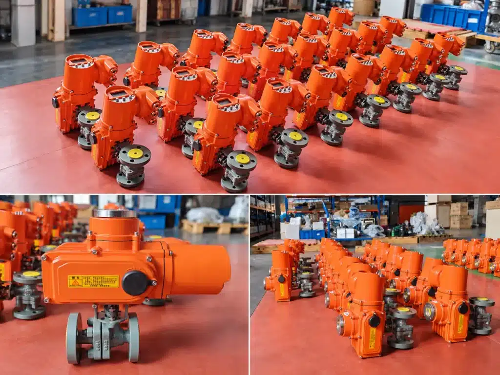
FLEYENDA / INDUSTRIAL VALVE SOLUTIONS
Actuator Valve Products & Solutions
Explore electric and pneumatic actuator solutions for industrial valve automation, including quarter-turn, multi-turn and other operating configurations.

01 / ELECTRIC QUARTER-TURN ACTUATOR
FLE Series Electric Actuator
Designed for compatible ball valves, butterfly valves and other rotary equipment. The FLE series supports industrial remote operation, with ON/OFF, modulating and intelligent control configurations available according to the selected model.
Typical applications: Water treatment, industrial pipelines, chemical processing and automated equipment.

02 / ELECTRIC ACTUATOR
QT Series Electric Actuator
A quarter-turn electric actuator solution for compatible rotary valves and industrial equipment. Its selection should be based on valve operating torque, mounting dimensions, operating frequency and required control functions.
Typical applications: Automated ball valve and butterfly valve operation.

03 / MULTI-TURN ACTUATOR
Z Series Electric Actuator
Designed for compatible multi-turn valve applications requiring repeated stem rotation. It can be considered for gate valves and other valve constructions that require multi-turn movement.
Typical applications: Industrial gate valves, utility pipelines and multi-turn valve automation.

04 / PNEUMATIC ACTUATOR
AT Series Pneumatic Actuator
A pneumatic quarter-turn actuator for compatible industrial valves. Compressed air drives its internal mechanism to generate rotary movement, with double-acting and spring-return configurations available according to the model.
Typical applications: Chemical processing, oil and gas, water treatment and industrial automation.
1. What Is an Actuator Valve?
An actuator valve is an industrial valve assembly equipped with a mechanical or electromechanical device that operates the valve automatically. The actuator receives a control command and converts energy into mechanical movement, which is transferred to the valve’s closure element.
Depending on the valve construction, this movement may rotate a ball or disc, turn a threaded stem, or move a valve plug in a linear direction. The resulting change in valve position controls whether the pipeline is open, closed or partially restricted.
A complete actuator valve assembly generally includes:
- Valve body: The pressure-containing component that connects to the pipeline.
- Closure element: The ball, disc, gate or plug that controls the flow passage.
- Stem or shaft: Transfers the actuator’s mechanical movement to the closure element.
- Actuator: Generates the torque or thrust required to operate the valve.
- Mounting components: Connect the actuator to the valve body and stem.
- Control accessories: Provide position feedback, switching signals or additional control functions when required.
It is important to distinguish between an actuator and an actuator valve. A valve actuator is the operating device itself, while an actuator valve refers to the complete valve-and-actuator assembly.
2. How Does an Actuator Valve Work?
The actuator valve working principle is based on converting an external energy source into controlled mechanical movement. The actuator receives an operating command, drives the valve mechanism and moves the closure element to the required position.
Step 1: Receiving the Control Command
The process begins when an operator or automation system sends a command. Depending on the actuator type, the command may be an electrical signal, compressed-air pressure or hydraulic control input.
In automated plants, a PLC, DCS or SCADA system can coordinate valve operation according to process conditions, equipment status and programmed operating sequences.
Step 2: Converting Energy into Mechanical Movement
The actuator converts its available energy into mechanical output. An electric actuator uses a motor and gearbox, a pneumatic actuator uses compressed air to move a piston or diaphragm, and a hydraulic actuator uses pressurized fluid to generate force.
Step 3: Transferring Movement to the Valve
The output is transferred through the mounting interface and valve stem. Depending on the design, the actuator generates rotary or linear movement.
For example, an electric actuator mounted on a ball valve rotates the stem and ball. A multi-turn actuator drives a threaded stem, while a linear pneumatic actuator moves a valve plug or stem along a straight path.
Step 4: Reaching and Maintaining the Required Position
Limit switches, position sensors, mechanical stops or control electronics help determine when the valve has reached its commanded position. Selected actuators also provide position feedback to the control system.
For modulating applications, a compatible actuator and position-control system can adjust the valve opening in response to changing process requirements.
3. Main Types of Actuator Valves
Industrial actuator valves are commonly classified by their power source. The main options are electric, pneumatic and hydraulic actuators. Spring-return configurations are also used where a predetermined valve position is required after a loss of operating power or air supply.
Electric Actuator Valve
An electric actuator valve uses an electric motor to generate the movement required to operate a valve. The motor’s output passes through a reduction gearbox, which increases usable torque and controls the movement speed.
Electric actuators are available in different configurations, including quarter-turn, multi-turn and selected linear arrangements. They can support remote ON/OFF operation, proportional positioning and integration with industrial control systems.
Typical applications:
- Water and wastewater treatment systems.
- Industrial process pipelines.
- HVAC and building automation.
- Chemical processing and utility systems.
- Automated equipment and production lines.
Main advantages: No compressed-air supply is required, electrical control is convenient, and selected models support position feedback and modulating operation.
Pneumatic Actuator Valve
A pneumatic actuator valve operates using compressed air. Air pressure enters the actuator chamber and moves a piston, rack-and-pinion mechanism or diaphragm, depending on the actuator design.
For quarter-turn valves, a pneumatic rack-and-pinion or scotch-yoke mechanism converts piston movement into shaft rotation. For globe and other linear valves, pneumatic diaphragm or piston actuators generate straight-line movement.
Double-acting actuators use compressed air to drive movement in both directions. Spring-return actuators use air pressure in one direction and a mechanical spring to return the valve when the air supply is removed.
Typical applications:
- High-cycle industrial production lines.
- Oil and gas processing.
- Chemical and petrochemical plants.
- Automated packaging and manufacturing equipment.
- Selected hazardous-area installations with suitable valve and accessory configurations.
Main advantages: Fast operation, simple mechanical construction and the ability to provide spring-return fail-safe configurations.
Hydraulic Actuator Valve
Hydraulic actuators use pressurized hydraulic fluid to generate mechanical force. A hydraulic piston or cylinder transfers this force to the valve stem or shaft.
Because hydraulic systems can generate high output force, they are commonly considered for large valves, heavy-duty equipment and applications where substantial torque or thrust is required.
Typical applications:
- Large pipeline and heavy industrial systems.
- Power generation facilities.
- Offshore and marine equipment.
- Heavy machinery and specialized process installations.
Main advantages: High force output and suitability for demanding mechanical loads. However, hydraulic power units, fluid management and additional maintenance must be considered.
Spring-Return Actuator Valve
A spring-return actuator uses stored mechanical energy in a spring to move the valve toward a predetermined position when the operating power or air supply is lost.
Depending on the actuator design, the fail position may be open or closed. This configuration is particularly important in emergency isolation and process safety applications.
Spring-return functionality is a specific actuator arrangement rather than a separate valve body type. The required fail position, available torque and operating conditions must be verified during selection.
4. Electric vs. Pneumatic vs. Hydraulic Actuator Valves
Each actuator technology has different operating characteristics. The best choice depends on available utilities, required operating speed, output force, control accuracy, environmental conditions and maintenance requirements.
| Comparison | Electric | Pneumatic | Hydraulic |
|---|---|---|---|
| Energy source | Electric power | Compressed air | Pressurized hydraulic fluid |
| Movement | Rotary or linear | Rotary or linear | Rotary or linear |
| Control | ON/OFF and selected modulating | ON/OFF and position control with accessories | ON/OFF and proportional control |
| Response | Depends on motor and gearbox | Often fast | Depends on hydraulic system |
| Force output | Depends on actuator size | Depends on air pressure and piston area | Suitable for high-force duties |
| Utilities | Electrical supply | Compressed-air system | Hydraulic power unit |
| Typical use | Industrial automation and remote control | Frequent cycling and process automation | Large and heavy-duty valves |
Electric actuators are often suitable when electrical power is readily available and remote positioning is important. Pneumatic actuators are attractive when a compressed-air network already exists or rapid cycling is required. Hydraulic actuators are generally reserved for applications requiring substantial force or specialized heavy-duty operation.
5. Different Valve Types Used with Actuators
The actuator is only one part of the complete assembly. The valve body and internal closure design determine the flow characteristics, pressure capability and suitability for the process.
Actuated Ball Valve
Ball valves use a rotating ball with a bore through its center. A quarter-turn actuator typically rotates the ball to open or close the flow passage.
Two-way ball valves are widely used for pipeline isolation, while three-way configurations can redirect or distribute flow through selected ports. V-port ball valves can also be designed for modulating flow applications.
Actuated Butterfly Valve
Butterfly valves use a rotating disc mounted inside the valve body. A quarter-turn actuator rotates the disc to control the flow passage.
They are commonly selected for larger pipeline diameters where compact construction, reduced weight and efficient installation are important.
Actuated Gate Valve
Gate valves use a movable gate that travels vertically to open or close the flow passage. They normally require multi-turn actuation rather than a simple quarter-turn movement.
They are generally selected for isolation duties where a full-open or full-closed flow path is required.
Actuated Globe Valve
Globe valves regulate flow through the movement of a plug or disc relative to a stationary seat. Their internal flow path is designed to support throttling and process regulation.
Electric or pneumatic linear actuators can be used to position the valve plug according to the control requirement.
Actuated Knife Gate Valve
Knife gate valves use a moving blade to isolate suitable fluids containing solids, slurry or fibrous materials. They are used in wastewater, mining, pulp and paper, and other solids-handling processes.
Linear pneumatic or electric actuation can be selected according to the required thrust, operating frequency and process conditions.
6. Rotary, Multi-Turn and Linear Actuators: What Is the Difference?
Another important classification is the type of movement generated by the actuator. The movement must match the mechanical requirements of the valve.
Quarter-Turn Actuator
A quarter-turn actuator typically rotates the valve shaft through approximately 90 degrees. It is commonly used with ball valves and butterfly valves.
Electric FLE series actuators and pneumatic rack-and-pinion actuators are examples of this arrangement.
Multi-Turn Actuator
A multi-turn actuator rotates the valve stem through multiple revolutions. It is suitable for gate valves and other valve designs that require threaded-stem movement.
The actuator must provide sufficient torque and travel to achieve the required valve position without overloading the stem or mechanical components.
Linear Actuator
A linear actuator generates straight-line movement rather than shaft rotation. It is commonly used with globe valves, control valves and certain gate or knife gate valve designs.
Its output thrust and travel must be matched to the valve’s operating requirements.
7. ON/OFF, Modulating and Fail-Safe Control
Actuator selection also depends on how the valve will be controlled by the plant automation system.
ON/OFF Control
ON/OFF actuators operate between defined open and closed positions. They are used for pipeline isolation, equipment switching and automated process sequences.
Modulating Control
Modulating actuators accept a proportional command, commonly 4–20 mA or 0–10 V on compatible electric actuator models. The control system uses this signal to request a particular valve position.
However, modulating capability alone does not guarantee accurate flow regulation. The valve characteristic, Cv/Kv sizing, pressure differential and control-loop configuration must also be considered.
Position Feedback
Position feedback allows a PLC, DCS or SCADA system to monitor whether the valve has reached the required position. Depending on the actuator, feedback may use limit contacts, potentiometers, position transmitters or digital communication.
Fail-Safe Operation
Some applications require the valve to move to a predetermined position after power or air failure. Common requirements include fail-open, fail-closed or maintaining the last position.
The required action must be defined in the control philosophy. Standard electric actuators do not automatically provide fail-open or fail-closed operation without a suitable fail-safe design.
8. How to Choose the Right Actuator Valve
Choosing an actuator valve requires matching the valve construction and actuator output to the actual process conditions. The following factors should be confirmed before requesting a quotation.
1. Identify the Operating Medium
Determine whether the valve will handle water, gas, steam, oil, chemicals, slurry or another process medium. Material compatibility should cover the valve body, closure element, seats, seals and other wetted components.
2. Confirm Pressure and Temperature
Specify normal operating conditions as well as the maximum design pressure and temperature. These parameters determine the suitable valve construction, pressure rating and sealing materials.
3. Select the Valve Structure
Choose a ball, butterfly, gate, globe or knife gate valve according to the required isolation or regulation function. Consider pipeline size, available installation space, pressure loss and flow characteristics.
4. Calculate Required Torque or Thrust
Quarter-turn valves require rotational torque, while linear valves require thrust. The calculation should consider differential pressure, seat friction, packing resistance, operating temperature and the valve manufacturer’s recommended safety margin.
5. Match the Actuator and Control System
Confirm the energy source, power supply, air pressure where applicable, control signals, position feedback, operating time and required fail action. Verify that the mounting interface is mechanically compatible with the valve.
6. Consider the Installation Environment
Outdoor installations, high-humidity locations, corrosive atmospheres and hazardous areas may require additional protection. Check the specific enclosure rating and explosion-proof certification for the complete actuator configuration.
7. Evaluate Maintenance and Operating Frequency
Consider the number of operating cycles, access for maintenance, availability of spare parts and the long-term cost of the power supply or compressed-air system.
9. Common Applications of Actuator Valves
Actuator valves are used in many industrial processes because they allow pipelines and equipment to be controlled remotely or automatically.
Water and Wastewater Treatment
Electric and pneumatic valves are used for water distribution, pump isolation, filtration, chemical dosing and wastewater process control. Valve construction should be selected according to water chemistry and suspended-solids content.
Oil and Gas
Actuated ball, gate and globe valves support pipeline isolation, process switching and flow regulation. Pressure rating, material compatibility and hazardous-area requirements are key selection considerations.
Chemical and Petrochemical Processing
Actuated valves control the movement of process liquids and gases through storage, reaction, transfer and treatment systems. Corrosion resistance, sealing performance and actuator protection must be evaluated.
Power Generation
Gate, globe and other actuated valves are used in utility and process systems. Steam pressure, operating temperature, valve thrust and control requirements influence the final configuration.
Food and Pharmaceutical Manufacturing
Sanitary valve assemblies with compatible electric or pneumatic actuators can be used in automated production lines. Hygienic design, cleanability, material certification and process compatibility are important.
10. Frequently Asked Questions About Actuator Valves
What is the difference between an actuator and an actuator valve?
An actuator is the device that generates mechanical movement. An actuator valve is the complete assembly consisting of a valve body, actuator and the required mounting or control components.
What are the main types of actuator valves?
The main types are electric actuator valves, pneumatic actuator valves and hydraulic actuator valves. Spring-return configurations are also used when a defined fail position is required.
How does an electric actuator valve work?
An electric motor drives a gearbox that generates the torque or thrust needed to move the valve. Control electronics and position sensors help operate the valve and monitor its position.
Which is better, an electric or pneumatic actuator valve?
Neither is universally better. Electric actuators are suitable when electrical power and remote positioning are priorities. Pneumatic actuators are useful where compressed air is available and rapid cycling or spring-return operation is required.
What is a quarter-turn actuator?
A quarter-turn actuator rotates a valve shaft through approximately 90 degrees. It is commonly used with ball valves and butterfly valves.
Can an actuator valve regulate flow?
Yes, when the valve construction and actuator support modulating control. Accurate flow regulation requires suitable valve characteristics, Cv/Kv sizing, actuator positioning and control-loop configuration.
What does fail-safe mean in an actuator valve?
Fail-safe operation means the valve moves to a predetermined position when the operating power or air supply fails. Common requirements include fail-open and fail-closed configurations.
How do I select the correct actuator size?
Actuator sizing should be based on the valve manufacturer’s torque or thrust requirements under actual operating conditions, including differential pressure, friction, temperature and required operating frequency.
Find the Right Actuator Valve for Your Industrial Application
Understanding the actuator valve working principle is the first step toward reliable industrial automation. The correct solution depends on more than the actuator’s power source. Valve construction, operating movement, torque or thrust, control requirements and installation conditions must all work together.
Fleyenda provides electric and pneumatic actuator solutions alongside industrial valve assemblies for water treatment, chemical processing, oil and gas, power generation and manufacturing applications.
Whether you need an electric actuated ball valve, pneumatic butterfly valve, multi-turn gate valve actuator or a complete automated control valve assembly, our team can help evaluate the appropriate configuration.
Share your valve type, size, medium, pressure, temperature and control requirements to discuss a suitable solution.