


How Does a Flow Control Valve Work?
A flow control valve is a precision device used to regulate the flow rate of liquids or gases in industrial pipelines, processing equipment, water systems, compressed air circuits, and automated machinery. Its primary function is to control how much fluid passes through a system within a specific period of time. Although the design may look simple from the outside, the working principle of a flow control valve is based on fluid dynamics, pressure differential, valve opening area, actuator response, and system demand.
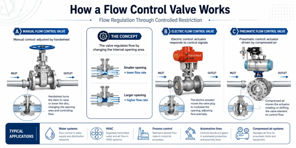
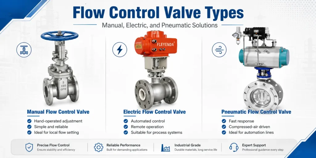
In practical applications, a flow control valve can be operated manually, electrically, or pneumatically. A manual flow control valve is adjusted by hand and is suitable for stable systems where frequent automation is not required. An electric flow control valve uses an electric actuator or control signal to regulate flow automatically. A pneumatic flow control valve uses compressed air as the driving force and is widely used in automation lines, packaging equipment, and air control systems.
What Is a Flow Control Valve?
A flow control valve is a valve designed to adjust, limit, or maintain the flow rate of a fluid. The controlled medium may be water, compressed air, steam, process gas, chemical liquid, coolant, fuel, or other compatible media. By changing the opening inside the valve body, the valve increases or decreases resistance to fluid movement.
In industrial systems, stable flow is essential for product quality, equipment efficiency, and process safety. For example, a water flow control valve can regulate cooling water in a heat exchanger. An air flow control valve can adjust the speed of a pneumatic cylinder. An electric flow control valve can automatically respond to signals from a PLC, temperature controller, or process control system.
This is why search terms such as how does a flow control valve work, flow control valve working principle, adjustable flow control valve, automatic flow control valve, and industrial flow control valve applications are commonly used by engineers, buyers, and maintenance teams.
Flow Control Valve Working Principle
The basic working principle of a flow control valve is controlled restriction. Inside the valve, the fluid passes through an internal opening such as an orifice, slot, needle seat, ball port, plug passage, or specially shaped flow channel. When this passage becomes smaller, flow resistance increases and the flow rate decreases. When the passage becomes larger, resistance decreases and the flow rate increases.
A simplified flow relationship can be expressed as:
Q = C × A × √(ΔP / ρ)
In this equation, Q represents flow rate, A is the effective opening area, ΔP is the pressure difference across the valve, ρ is fluid density, and C is a coefficient related to valve geometry and flow characteristics. This formula shows that flow is affected not only by the valve opening, but also by pressure difference and fluid properties.
For this reason, two valves with the same opening may deliver different flow rates if the upstream pressure, downstream pressure, viscosity, temperature, or media type changes. A good flow control valve design must therefore consider both mechanical structure and operating conditions.
Main Components of a Flow Control Valve
Although different flow control valve types have different structures, most designs include several core components:
- Valve body: The main housing that contains the flow path and withstands system pressure.
- Flow control element: A needle, plug, ball, disc, spool, or cartridge that changes the opening area.
- Seat or orifice: The precision area where flow restriction occurs.
- Stem or shaft: The mechanical link that transfers motion to the control element.
- Actuator or handle: The part that moves the valve, either manually, electrically, or pneumatically.
- Seals and packing: Components that prevent leakage and maintain pressure integrity.
The quality of these components affects flow accuracy, response speed, sealing performance, corrosion resistance, and service life. For demanding applications, material selection is also important. Brass, stainless steel, carbon steel, aluminum alloy, engineering plastic, and special alloys may be selected according to the medium, temperature, pressure, and working environment.
Manual Flow Control Valve
A manual flow control valve is operated by hand through a knob, lever, wheel, or screw mechanism. The operator adjusts the opening according to the required flow rate. This type is simple, reliable, and cost-effective, making it suitable for systems where flow settings do not need to change frequently.
Manual flow control valves are commonly used in water supply lines, cooling circuits, laboratory equipment, irrigation systems, small process lines, and general industrial pipelines. Because the adjustment is mechanical, there is no need for external power, control wiring, or compressed air supply.
How a Manual Flow Control Valve Works
In a manual valve, turning the handle changes the position of the internal control element. For example, in a needle type manual flow control valve, the tapered needle moves closer to or farther away from the seat. When the needle moves toward the seat, the flow passage becomes smaller and the flow rate decreases. When the needle moves away from the seat, the passage becomes larger and flow increases.
The main advantage of a manual adjustable flow control valve is its simplicity. It is easy to install, easy to maintain, and suitable for direct on-site adjustment. However, it is not ideal for systems that require remote operation, frequent flow changes, or automatic feedback control.
Electric Flow Control Valve
An electric flow control valve uses an electric actuator, motor, or solenoid-driven mechanism to adjust the valve opening. It can receive control signals from a PLC, sensor, control panel, building management system, or industrial automation controller. This makes it suitable for automatic flow regulation and remote operation.
Electric flow control valves are widely used in HVAC systems, water treatment plants, chemical processing, food and beverage production, cooling systems, dosing systems, and smart industrial equipment. They are especially useful when flow must be adjusted according to temperature, pressure, level, production demand, or process feedback.
How an Electric Flow Control Valve Works
In an electric flow control valve, the control signal drives the actuator. The actuator converts electrical energy into mechanical motion, such as rotary movement or linear movement. This motion changes the position of the valve plug, ball, disc, or stem, which then changes the internal flow passage.
Some electric valves provide simple open-close control, while others offer proportional flow control. A proportional electric flow control valve can adjust to intermediate positions, such as 20%, 50%, or 75% open. This allows more accurate flow regulation than a basic on-off valve.
Compared with manual valves, electric flow control valves provide better automation capability, repeatability, and remote control. However, they require power supply, control wiring, proper actuator sizing, and protection against moisture, dust, vibration, or high-temperature environments.
Pneumatic Flow Control Valve
A pneumatic flow control valve uses compressed air to operate the valve or regulate air flow in a pneumatic circuit. In many automation systems, pneumatic flow control valves are used to control the speed of cylinders, actuators, grippers, and air-driven tools.
Pneumatic valves are popular because compressed air systems are clean, fast, and suitable for repetitive motion. They are commonly used in packaging machinery, assembly lines, textile machines, printing equipment, material handling systems, and robotic end-of-arm tooling.
How a Pneumatic Flow Control Valve Works
A pneumatic flow control valve typically regulates compressed air by restricting the passage through which air enters or leaves an actuator. When the passage is narrowed, the actuator moves more slowly. When the passage is enlarged, the actuator moves faster.
One common design is the one-way pneumatic flow control valve, also known as a pneumatic speed controller. It combines a flow restriction with a check valve. In one direction, air passes through the adjustable restriction. In the opposite direction, air bypasses the restriction through the check valve. This allows separate control of forward and return motion.
Because air is compressible, pneumatic flow control requires careful adjustment. If the valve is opened too much, actuator motion may become too fast or unstable. If it is closed too much, movement may become slow, weak, or delayed. Correct adjustment improves smoothness, cycle time, and equipment reliability.
Manual vs Electric vs Pneumatic Flow Control Valve
Choosing between manual, electric, and pneumatic flow control valves depends on the application requirements. Each type has its own advantages and limitations.
- Manual flow control valve: Best for simple systems, local adjustment, low cost, and stable operating conditions.
- Electric flow control valve: Best for automation, remote control, proportional adjustment, and process integration.
- Pneumatic flow control valve: Best for compressed air systems, fast actuator speed control, and repetitive machine motion.
For a basic water line, a manual flow control valve may be enough. For a smart cooling or dosing system, an electric flow control valve may be more suitable. For controlling the speed of an air cylinder, a pneumatic flow control valve is usually the practical choice.
Common Flow Control Valve Applications
Flow control valves are used in many industries where stable and predictable flow is required. Common flow control valve applications include:
- Water treatment and filtration systems
- Cooling water and temperature control circuits
- Compressed air systems and pneumatic automation
- HVAC systems and building services
- Chemical dosing and process control
- Food and beverage production lines
- Laboratory testing and analytical instruments
- Packaging, printing, and assembly machinery
In each application, the flow control valve must be selected based on media compatibility, pressure rating, flow range, connection size, sealing material, control method, and environmental conditions.
Flow Control Valve Troubleshooting
Effective flow control valve troubleshooting starts with identifying the symptom. If the flow is too low, possible causes include incorrect adjustment, blocked orifice, clogged filter, undersized valve, low supply pressure, or excessive downstream resistance.
If the flow is unstable, the cause may be pressure fluctuation, air trapped in the system, worn internal parts, vibration, contamination, or incorrect valve selection. If the valve leaks, check the seals, packing, seat surface, connection fittings, and installation direction.
How to Select the Right Flow Control Valve
To select the right flow control valve, engineers and buyers should consider the required flow range, working pressure, media type, temperature, viscosity, control accuracy, response time, installation space, and maintenance requirements.
For simple local control, choose a manual adjustable flow control valve. For automatic process control, choose an electric flow control valve with the correct signal type and actuator torque. For compressed air motion control, choose a pneumatic flow control valve or one-way speed controller that matches the tubing size and actuator requirements.
It is also important to avoid oversizing. A valve that is too large may be difficult to adjust accurately at low flow rates. A valve that is too small may create excessive pressure drop, noise, vibration, or unstable operation.
Conclusion
A flow control valve works by changing the effective flow passage inside the valve body, creating a controlled restriction that regulates the movement of liquids or gases. Its performance depends on valve opening, pressure difference, fluid properties, internal geometry, and control method.
Manual, electric, and pneumatic flow control valves serve different engineering needs. A manual flow control valve offers simple and reliable local adjustment. An electric flow control valve provides automation and remote control. A pneumatic flow control valve is ideal for compressed air systems and actuator speed regulation. Understanding these differences helps engineers, technicians, and buyers choose the right valve for safer, more efficient, and more stable system operation.