


Industrial Valve Guide
What is a Globe Valve
A globe valve is one of the most widely used linear motion valves in industrial piping systems, especially where accurate flow regulation, reliable shutoff, and long-term sealing performance are required. Unlike valves designed only for quick isolation, a globe valve is engineered to control, throttle, and stop fluid flow with a high degree of precision.
What Is a Globe Valve?
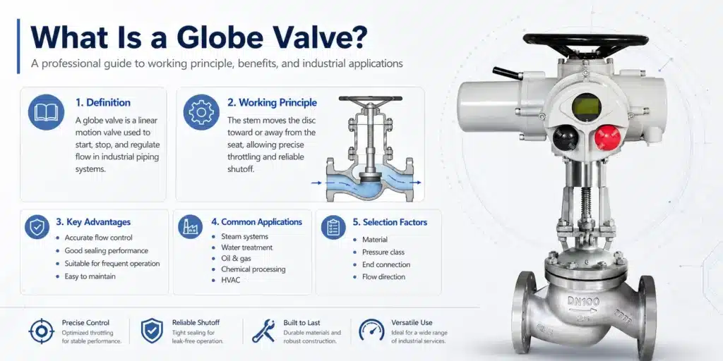
A globe valve is a type of valve used to start, stop, and regulate the flow of liquids, gases, steam, and other process media. It gets its name from the rounded, globe-like shape of early valve bodies, although modern globe valves may have straight, angle, or Y-pattern designs. The key feature of a globe valve is its internal flow path: the fluid changes direction as it passes through the valve body, moving around a seat and disc assembly.
In practical terms, a globe valve is valued for its ability to provide controlled flow adjustment. When the handwheel or actuator moves the stem, the disc moves toward or away from the seat. This changes the size of the flow opening and allows operators to regulate flow rate, pressure, and system performance. Because of this design, globe valves are commonly used in steam lines, cooling water systems, fuel oil systems, chemical processing plants, power plants, HVAC systems, and general industrial pipelines.
For engineers, buyers, and maintenance teams, understanding what a globe valve is goes beyond a simple definition. It also requires knowledge of the valve’s working principle, structure, materials, pressure drop, advantages, limitations, and correct installation practices.
How Does a Globe Valve Work?
The basic globe valve working principle is simple but highly effective. A movable disc, also called a plug, closes against a stationary seat inside the valve body. The disc is connected to a stem, and the stem is operated by a handwheel, gearbox, electric actuator, pneumatic actuator, or hydraulic actuator. When the stem rises, the disc lifts away from the seat and allows fluid to pass. When the stem moves downward, the disc approaches the seat and restricts or stops the flow.
This linear movement gives a globe valve excellent throttling capability. Unlike a gate valve, which is mainly designed for fully open or fully closed service, a globe valve can operate at intermediate positions. This makes it suitable for flow control applications where the operator needs to adjust the process gradually.
However, the internal flow path of a globe valve creates more resistance than some other valve types. As fluid enters the valve, changes direction, passes through the seat area, and exits the body, pressure loss occurs. This is why globe valve pressure drop must be considered when designing a piping system. In applications where precise control is more important than minimum pressure loss, the globe valve remains an excellent choice.
Main Globe Valve Parts and Functions
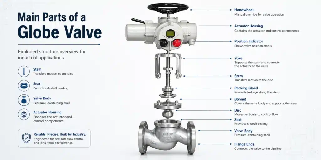
A standard globe valve is made up of several important components. Each part affects performance, durability, sealing ability, and maintenance requirements.
Valve Body
The body is the main pressure-containing component. It holds the internal parts and connects to the pipeline through flanged, threaded, welded, or socket-weld ends.
Bonnet
The bonnet covers the valve body and supports the stem assembly. It may be bolted, welded, pressure-sealed, or screwed depending on pressure class and application.
Disc or Plug
The disc controls the flow by moving toward or away from the seat. Different disc designs are used for shutoff, throttling, or high-temperature service.
Seat
The seat provides the sealing surface. High-quality seat design is critical for globe valve sealing performance and leakage prevention.
Stem
The stem connects the handwheel or actuator to the disc. It transfers linear movement and must resist corrosion, wear, and mechanical stress.
Packing
Packing seals the area around the stem to prevent external leakage. Proper packing selection is essential for steam, chemical, and high-pressure applications.
Common Globe Valve Types
There are several globe valve types, and each design is suitable for different operating conditions. Selecting the correct type improves system efficiency, reduces maintenance costs, and extends valve service life.
Straight Pattern Globe Valve
A straight pattern globe valve, also known as a T-pattern globe valve, has inlet and outlet ports aligned in a straight line. It is the most common design and is widely used in general industrial service. Its main advantage is reliable control, but it usually has a relatively higher pressure drop.
Angle Globe Valve
An angle globe valve changes the direction of flow by 90 degrees. It can replace both a valve and a pipeline elbow in certain piping layouts. Angle globe valves are often used in applications involving pulsating flow, steam service, or systems where space-saving installation is important.
Y-Pattern Globe Valve
A Y-pattern globe valve is designed to reduce flow resistance. Its seat and stem are positioned at an angle, creating a smoother flow path than a straight pattern valve. This type is often selected for high-pressure service where lower pressure drop and better flow efficiency are important.
Flanged Globe Valve
A flanged globe valve uses flanged end connections for easy installation, inspection, and removal. It is commonly found in industrial plants, water treatment systems, oil and gas facilities, and power generation pipelines. Flanged ends are especially useful for larger valve sizes and higher-pressure systems.
Stainless Steel Globe Valve
A stainless steel globe valve offers excellent corrosion resistance and is suitable for chemical processing, food and beverage systems, marine environments, and clean water applications. Materials such as CF8, CF8M, SS304, and SS316 are commonly used depending on the media and operating conditions.
Globe Valve for Flow Control
One of the strongest reasons to use a globe valve for flow control is its stable throttling performance. The disc movement is proportional and predictable, allowing operators to make fine adjustments. This is valuable in systems where pressure, temperature, or flow rate must be carefully managed.
In steam systems, for example, globe valves can regulate steam supply to equipment. In cooling water systems, they can balance flow across different branches. In chemical plants, they help control the delivery of process fluids. In HVAC systems, they can be used to regulate water flow through heating and cooling circuits.
Although control valves with advanced actuators are used for automated precision control, manual globe valves remain a dependable solution for many industrial and commercial applications. Their design gives maintenance teams a familiar, serviceable, and robust valve option.
Globe Valve vs Gate Valve
A common question in valve selection is the difference between a globe valve and a gate valve. Both are linear motion valves, but they are designed for different purposes.
A gate valve is mainly used for isolation. When fully open, it allows nearly straight-through flow with low pressure drop. However, it is not recommended for throttling because partial opening may cause vibration, seat damage, and erosion. A globe valve, on the other hand, is designed for both shutoff and flow regulation. Its disc and seat arrangement makes it much better for throttling service.
The trade-off is pressure loss. A globe valve typically creates a higher pressure drop than a gate valve because the fluid changes direction inside the body. Therefore, if the application requires minimum flow resistance and only on-off operation, a gate valve may be suitable. If the system requires flow adjustment, pressure regulation, or frequent operation, a globe valve is often the better choice.
| Comparison Item | Globe Valve | Gate Valve |
|---|---|---|
| Main Function | Flow control and shutoff | On-off isolation |
| Throttling Ability | Excellent | Poor |
| Pressure Drop | Higher | Lower |
| Flow Path | Changes direction | Mostly straight |
| Best Use | Regulation and frequent operation | Full-open or full-close service |
Industrial Globe Valve Applications
Industrial globe valve applications cover a wide range of systems. Because globe valves can handle different pressures, temperatures, and media, they are used in many industries where controlled flow is required.
- Steam pipelines and boiler systems
- Power generation plants
- Oil and gas processing facilities
- Chemical and petrochemical plants
- Water treatment and wastewater systems
- HVAC heating and cooling systems
- Marine piping systems
- Fuel oil and lubrication systems
- Compressed air and gas systems
In these applications, globe valves are often selected where system reliability, controllability, and maintenance access are important. The valve may be installed as a manual valve, automated valve, drain valve, bypass valve, or balancing valve depending on the project requirements.
Advantages and Disadvantages of Globe Valves
Like all industrial valves, globe valves have strengths and limitations. A professional selection process should consider both.
Advantages
- Excellent throttling and flow regulation capability
- Good shutoff performance when properly designed and maintained
- Shorter stem travel compared with some other linear valves
- Suitable for frequent operation
- Available in many materials, pressure classes, and end connections
- Relatively easy to inspect and repair compared with more complex valves
Disadvantages
- Higher pressure drop than gate valves and ball valves
- Usually requires more operating force
- Not ideal for large pipelines where low resistance is critical
- Improper installation direction can reduce performance
- Throttling under severe conditions may cause seat or disc wear
How to Choose a Globe Valve
Knowing how to choose a globe valve is essential for safe and efficient system operation. The correct valve depends on the service conditions, media characteristics, operating pressure, temperature, flow requirements, and maintenance expectations.
1. Confirm the Media
The first step is to identify the fluid or gas flowing through the system. Water, steam, oil, gas, acid, alkali, and corrosive chemicals all require different material choices. For corrosive media, a stainless steel globe valve or special alloy valve may be required.
2. Check Pressure and Temperature
Globe valves must be rated for the system’s pressure and temperature. Common pressure classes include Class 150, Class 300, Class 600, Class 900, and higher. For high-temperature steam or power plant service, the body, bonnet, trim, packing, and gasket materials must all be suitable.
3. Select the Right Body Material
Globe valve material selection may include cast iron, ductile iron, carbon steel, stainless steel, bronze, alloy steel, or special alloys. Carbon steel is often used for general industrial service, while stainless steel is preferred for corrosive or sanitary environments.
4. Consider End Connections
End connections should match the piping design. Flanged globe valves are common in industrial pipelines because they are easy to remove and service. Threaded and socket-weld valves are often used for smaller sizes, while butt-weld valves are preferred in high-pressure or high-temperature systems.
5. Evaluate Flow Control Requirements
If accurate throttling is required, disc design and flow characteristics become important. Needle-type, parabolic, or specially designed discs may be selected for improved control. For simple on-off and moderate throttling service, a standard plug disc may be sufficient.
6. Use a Globe Valve Sizing Guide
Globe valve sizing should not be based only on pipe diameter. Engineers should consider flow rate, pressure drop, fluid density, viscosity, temperature, and required control range. Oversized valves may control poorly at low openings, while undersized valves may create excessive pressure loss and noise.
Globe Valve Installation Guide
Correct installation is critical to valve performance and service life. Before installation, inspect the valve for damage, confirm the pressure rating, check the flow direction marking, and ensure the pipeline is clean.
Most globe valves have a preferred flow direction, usually indicated by an arrow on the valve body. Installing the valve in the wrong direction can increase operating torque, reduce sealing performance, and shorten component life. The valve should be installed in a position that allows enough space for handwheel operation, stem movement, actuator access, and future maintenance.
During installation, avoid using the valve as a pipe support. Pipeline stress, misalignment, or vibration can damage the body, seat, stem, and packing. For flanged globe valves, bolts should be tightened evenly in a cross pattern. Gaskets must be compatible with the media, pressure, and temperature.
Globe Valve Maintenance Tips
Regular maintenance helps maintain sealing performance and prevents unexpected downtime. Globe valve maintenance tips include periodic inspection, packing adjustment, lubrication of moving parts, leakage checks, and verification of operating condition.
Operators should check for external leakage around the stem packing and bonnet gasket. If leakage appears at the packing area, the gland may need careful adjustment. Over-tightening should be avoided because it can increase stem friction and accelerate wear. Internal leakage may indicate disc or seat damage, foreign particles, erosion, or improper closure.
For valves in severe service, maintenance intervals should be shorter. High-temperature steam, corrosive chemicals, abrasive fluids, and frequent throttling can all increase wear. Keeping accurate maintenance records helps identify repeated issues and supports better replacement planning.
Globe Valve Troubleshooting
Common globe valve troubleshooting issues include leakage, hard operation, vibration, noise, and poor flow control. Each problem should be diagnosed carefully before repair.
- Stem leakage: Check packing condition and gland adjustment.
- Seat leakage: Inspect the disc, seat surface, and trapped debris.
- Hard operation: Check stem lubrication, packing tightness, corrosion, or actuator problems.
- Noise or vibration: Review flow velocity, pressure drop, cavitation, and throttling position.
- Poor control: Confirm correct valve sizing, disc type, and operating range.
In many cases, small problems can be solved through cleaning, adjustment, or replacement of soft components. However, severe seat damage, body corrosion, or pressure boundary defects may require valve replacement.
Conclusion
A globe valve is a reliable and versatile valve designed for flow control, throttling, and shutoff in industrial piping systems. Its linear motion design, disc-and-seat structure, and controllable opening make it especially useful where accurate regulation is needed. Although it usually creates a higher pressure drop than gate valves or ball valves, its advantages in control performance, sealing capability, and service flexibility make it an important choice across many industries.
When selecting a globe valve, engineers and buyers should consider media, pressure, temperature, body material, trim design, end connection, flow direction, and maintenance requirements. A properly selected and installed globe valve can improve process stability, reduce leakage risk, and deliver long service life in demanding applications.