


Characteristics and Classification of Globe Valve
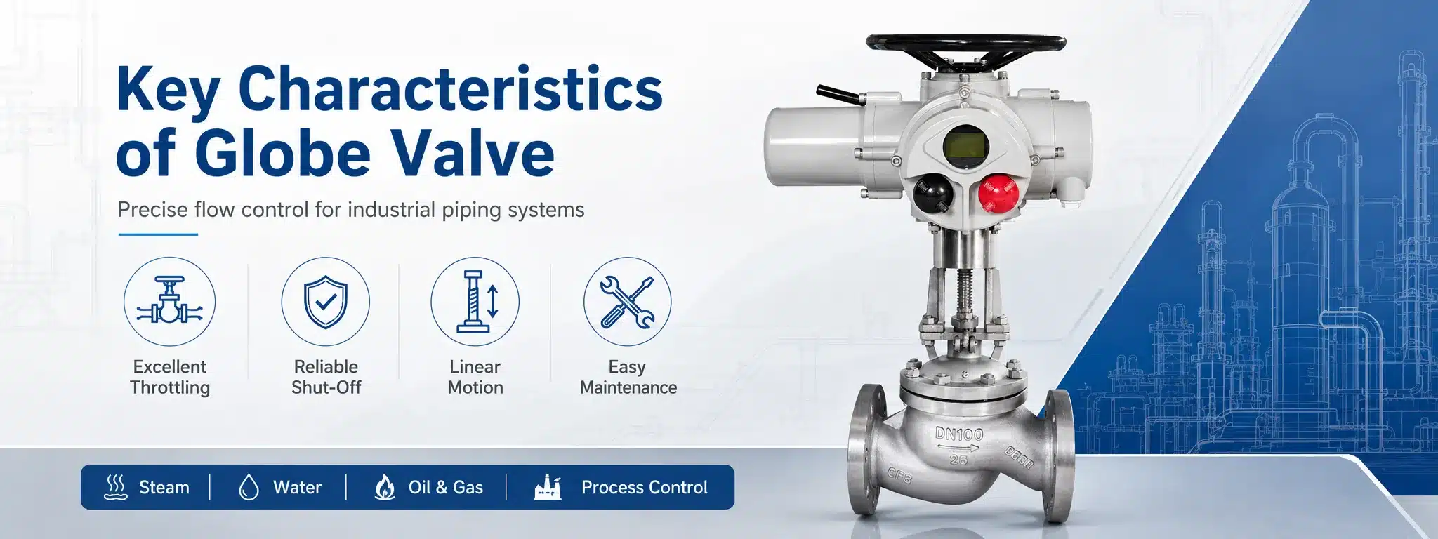
A globe valve is a linear motion valve widely used for stopping, starting, and regulating fluid flow in pipelines. Compared with many quarter-turn valves, a globe valve is especially valued for its excellent throttling ability, reliable shut-off performance, and precise flow control. It is commonly used in water systems, steam pipelines, oil and gas facilities, chemical processing plants, power stations, HVAC systems, boiler feedwater lines, and general industrial piping.
The name “globe valve” comes from the traditional spherical body shape of the valve. However, modern globe valves may have different body patterns and internal structures depending on the application. A typical globe valve contains a valve body, bonnet, stem, disc, seat, handwheel or actuator, and packing system. When the stem moves up or down, the disc moves toward or away from the seat, controlling the flow area inside the valve.
Understanding the characteristics and classification of globe valve products is important for correct valve selection. A globe valve can provide accurate control, but it also creates higher pressure drop than a gate valve or ball valve. Therefore, engineers and buyers should evaluate pressure rating, temperature, flow media, sealing requirements, installation direction, operation method, and maintenance conditions before choosing a valve.
What Is a Globe Valve?
A globe valve is a type of valve designed to control fluid flow by moving a disc or plug perpendicular to a fixed seat. When the disc is lifted away from the seat, fluid can pass through the valve. When the disc is pressed against the seat, the valve closes and stops flow. Because the disc position can be adjusted gradually, globe valves are highly suitable for throttling service.
In many industrial systems, globe valves are selected when flow regulation is more important than minimum pressure loss. A gate valve is usually better for fully open or fully closed service, while a ball valve is preferred for quick shut-off. A globe valve, however, gives operators better control over intermediate opening positions. This makes it useful for regulating steam, cooling water, fuel oil, compressed air, gas, and process fluids.
Globe valves are available in many materials, including cast iron, ductile iron, carbon steel, stainless steel, alloy steel, bronze, brass, and special corrosion-resistant alloys. Different sealing materials and trim designs can also be selected according to temperature, pressure, corrosion, erosion, and leakage requirements.
How Does a Globe Valve Work?
The working principle of a globe valve is based on linear movement. When the operator turns the handwheel, the stem moves upward or downward through the threaded mechanism. As the stem moves, it raises or lowers the disc. The disc then changes the opening between the disc and the seat, allowing more or less fluid to pass through.
When the globe valve is fully closed, the disc contacts the seat tightly and blocks the flow path. When the valve is partially open, the flow area is restricted, which allows flow regulation. When the valve is fully open, the disc is lifted away from the seat, but the fluid still changes direction inside the valve body. This internal flow path is one reason globe valves usually have a higher pressure drop than straight-through valves.
For automatic control systems, a globe control valve may be equipped with a pneumatic actuator, electric actuator, or hydraulic actuator. The actuator receives a control signal and adjusts the stem position. This allows the valve to regulate pressure, flow rate, temperature, or liquid level in process control loops.
Main Characteristics of Globe Valve
The most important characteristic of a globe valve is its strong throttling performance. The disc and seat design allows gradual flow adjustment, making the valve suitable for applications where flow must be controlled rather than simply turned on or off. This is why globe valves are often used as regulating valves in steam, water, gas, and oil systems.
Another key characteristic is reliable shut-off. When properly selected and maintained, a globe valve can provide good sealing performance. Different disc and seat materials can be used to improve sealing under high temperature, high pressure, or corrosive conditions. Soft-seated globe valves can offer tight shut-off in moderate service, while metal-seated globe valves are more suitable for high temperature and high pressure applications.
Globe valves also have a relatively simple and serviceable structure. The bonnet can often be removed for inspection, seat maintenance, packing replacement, or disc repair. This makes globe valves practical for plants where maintenance access and long service life are important.
However, a globe valve also has limitations. Because fluid changes direction inside the valve body, resistance is higher than in gate valves or ball valves. This means globe valves are not always ideal for systems requiring very low pressure drop. They may also require more operating torque, especially in large sizes or high-pressure systems.
| Characteristic | Description | Practical Meaning |
|---|---|---|
| Excellent throttling ability | The disc position can be adjusted gradually | Suitable for flow regulation and control service |
| Good shut-off performance | The disc closes directly against the seat | Helps prevent leakage when fully closed |
| Higher pressure drop | Fluid changes direction inside the valve body | Less suitable for applications requiring minimum resistance |
| Linear motion operation | The stem moves the disc up and down | Provides stable and accurate opening control |
| Easy maintenance | Bonnet, stem, disc, and packing can often be serviced | Useful for industrial systems requiring regular inspection |
Basic Structure of Globe Valve
A typical globe valve consists of a body, bonnet, stem, disc, seat ring, packing, gland, and operating device. The valve body contains the pressure boundary and internal flow passage. The bonnet connects to the body and supports the stem and packing system. The stem transfers force from the handwheel or actuator to the disc.
The disc is the moving closure element. It may be shaped as a plug disc, flat disc, needle disc, or composition disc depending on the service. The seat ring provides the sealing surface. When the disc contacts the seat, the flow is stopped. The packing system prevents leakage around the stem while allowing the stem to move.
In high-performance globe valves, the trim design is very important. “Trim” usually refers to the internal parts exposed to the flow, such as the disc, seat, stem, and guide surfaces. For high pressure drop, high velocity, steam, or erosive media, the trim must be selected carefully to prevent vibration, noise, cavitation, flashing, and premature wear.
Classification of Globe Valve
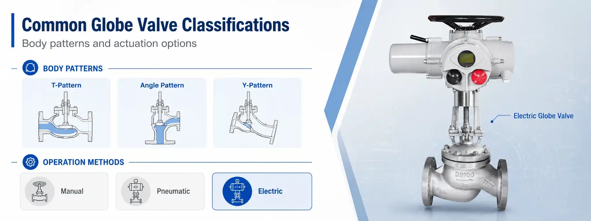
Globe valves can be classified in several ways. The most common classification methods are based on body pattern, disc design, bonnet construction, operation method, pressure rating, material, and application. Understanding these classifications helps users select the correct globe valve for different working conditions.
For example, a standard T-pattern globe valve may be used for general throttling service, while an angle globe valve may be chosen where the pipeline changes direction. A Y-pattern globe valve can reduce flow resistance compared with a conventional design. A pneumatic globe valve may be used in automated control systems, while a manual globe valve may be used for simple pipeline operation.
Classification by Body Pattern
T-Pattern Globe Valve
The T-pattern globe valve, also called a Z-pattern globe valve, is the most common type. In this design, the flow path changes direction inside the valve body. This structure provides good throttling control and reliable shut-off, but it also causes higher pressure drop. T-pattern globe valves are widely used in general industrial pipelines, steam systems, water lines, and process control applications.
Angle Globe Valve
An angle globe valve has inlet and outlet ports arranged at approximately 90 degrees. It can change the direction of pipeline flow while also performing shut-off or throttling. Because the flow path is less complex than some standard globe valve designs, an angle globe valve can reduce turbulence in certain applications. It is commonly used in boiler systems, steam service, drainage lines, and space-limited piping layouts.
Y-Pattern Globe Valve
A Y-pattern globe valve has the stem and seat positioned at an angle to the main flow path. This design reduces flow resistance compared with a standard T-pattern globe valve. Y-pattern globe valves are often used in high-pressure service, steam pipelines, and applications where both throttling ability and lower pressure drop are desired.
Straight-Through Globe Valve
Some globe valve designs use a more streamlined flow path to reduce resistance while maintaining regulating ability. These valves may be selected for systems where pressure loss must be controlled but a globe-style throttling function is still required.
Classification by Disc Design
Plug Disc Globe Valve
A plug disc globe valve uses a tapered or contoured disc to provide better throttling performance. The shape of the disc allows more gradual changes in flow as the valve opens or closes. This design is common in regulating service and process control systems.
Flat Disc Globe Valve
A flat disc design is simple and suitable for general shut-off applications. It is often used where precise throttling is not the main requirement. Although it can control flow to some degree, it is usually not as effective for fine regulation as a plug disc or needle design.
Needle Globe Valve
A needle globe valve uses a long, tapered needle-like disc to provide very fine flow adjustment. It is commonly used in instrumentation, sampling lines, laboratory systems, fuel control, and low-flow applications. Needle globe valves are ideal when small flow changes must be controlled accurately.
Composition Disc Globe Valve
A composition disc globe valve uses a softer sealing insert on the disc. This design can provide tighter shut-off when the operating temperature and media are compatible with the soft material. It is often used in air, water, and low-to-moderate temperature service.
Classification by Operation Method
A manual globe valve is operated by a handwheel. It is simple, reliable, and suitable for systems where frequent automatic adjustment is not required. Manual globe valves are commonly used in utility systems, plant pipelines, and maintenance lines.
A pneumatic globe valve uses compressed air to move the actuator and adjust the valve stem. It is widely used in automated process control because pneumatic actuators provide fast response, strong force, and reliable operation in industrial environments. Pneumatic globe control valves are common in chemical plants, power plants, refineries, and steam control systems.
An electric globe valve uses an electric actuator to control valve movement. It is suitable for remote operation, building automation, water treatment, HVAC systems, and applications where electrical control signals are preferred. Electric actuated globe valves can provide accurate positioning and are easy to integrate with control systems.
A hydraulic globe valve uses hydraulic pressure for actuation. This type is less common in general piping but may be used where high force and precise movement are required.
Common Applications of Globe Valves
Globe valves are used in systems that require reliable flow regulation or shut-off. In steam systems, they can control steam flow to heat exchangers, turbines, process equipment, and heating coils. In water systems, they regulate cooling water, boiler feedwater, service water, and process water. In oil and gas applications, globe valves can control fuel oil, lubricating oil, gas, and process fluids.
In power plants, globe valves are used in boiler feedwater lines, steam lines, condensate systems, drain systems, bypass lines, and auxiliary systems. Their ability to handle high temperature and high pressure makes them suitable for demanding energy applications. In chemical and petrochemical plants, stainless steel globe valves and alloy globe valves are selected for corrosive or high-temperature media.
Globe valves are also found in HVAC systems, fire protection systems, marine piping, pharmaceutical production, textile machinery, and general manufacturing facilities. When accurate flow control is required, a globe valve is often a practical and dependable choice.
How to Choose the Right Globe Valve
Selecting the right globe valve begins with understanding the working conditions. Important parameters include nominal size, pressure rating, temperature, flow media, flow rate, pressure drop, leakage class, end connection, valve material, and operation method. A valve used for clean water may require a very different design from a valve used for high-pressure steam or corrosive chemicals.
Material selection is especially important. Carbon steel globe valves are common in high-pressure industrial systems. Stainless steel globe valves provide better corrosion resistance. Bronze and brass globe valves are often used in water, air, and low-pressure service. Alloy steel globe valves may be required for high temperature, high pressure, or severe service.
The end connection should match the pipeline design. Flanged globe valves are common in industrial piping because they are easy to install and remove. Threaded globe valves are used in small-size systems. Welded globe valves are selected where leakage prevention and high-pressure reliability are critical.
The valve should also be sized correctly. Oversized globe valves may operate too close to the closed position, causing poor control, vibration, and seat wear. Undersized valves may create excessive pressure drop and limit system capacity. For control applications, proper valve sizing is essential for stable performance.
Installation and Maintenance Tips
Before installing a globe valve, check the flow direction marked on the valve body. Many globe valves are designed for flow in a specific direction, especially when used for pressure-assisted sealing or control stability. Installing the valve in the wrong direction can cause poor performance, leakage, noise, vibration, or increased operating force.
The pipeline should be clean before installation. Welding slag, sand, rust, and debris can damage the seat and disc. For steam and high-temperature systems, the valve should be warmed gradually to reduce thermal shock. Proper support should also be provided so that pipe stress does not overload the valve body or bonnet connection.
During maintenance, inspect the packing area for leakage, check the stem movement, verify handwheel or actuator operation, and examine the seat and disc if shut-off performance declines. Packing may need adjustment or replacement over time. If the valve is difficult to operate, the cause may be stem damage, packing friction, corrosion, debris, or excessive pressure differential.
In throttling applications, the seat and disc may experience erosion because fluid velocity is high near the restricted opening. Regular inspection is recommended for high-pressure drop service, steam service, or media containing particles. Preventive maintenance can extend service life and reduce unplanned shutdowns.
Conclusion
A globe valve is a reliable and versatile valve designed for shut-off and flow regulation. Its key characteristics include excellent throttling ability, good sealing performance, linear motion control, serviceable structure, and wide material availability. At the same time, users must consider its higher pressure drop and proper installation direction.
The classification of globe valve products can be based on body pattern, disc design, bonnet structure, operation method, material, pressure rating, and application. T-pattern globe valves, angle globe valves, Y-pattern globe valves, needle globe valves, pneumatic globe valves, electric globe valves, and flanged globe valves all serve different operating needs. By understanding these characteristics and classifications, engineers, buyers, and maintenance teams can choose the right globe valve for safe, efficient, and long-lasting pipeline performance.