


How Do Pneumatic Valves Work?
Pneumatic valves are essential control components in compressed air systems. They direct, start, stop, regulate, or exhaust air so that machines can perform controlled movement. In automation equipment, pneumatic cylinders, air tools, packaging machines, robotic grippers, and industrial production lines, pneumatic valves act like the decision-making points of an air circuit. They determine where compressed air goes, when it moves, how fast it flows, and how safely the system operates.
The basic idea is simple: compressed air enters a valve, and the valve changes the air path according to its internal design and control signal. That signal may come from a solenoid coil, manual lever, mechanical actuator, air pilot signal, or spring return. Although pneumatic valves can look small, they play a major role in system speed, accuracy, safety, and efficiency.
What Are Pneumatic Valves?
Pneumatic valves are devices used to control compressed air in pneumatic systems. A pneumatic system uses pressurized air as a power source to create motion, clamp parts, move products, operate tools, or control industrial processes. The valve is the component that manages this air. Without valves, compressed air would simply remain stored in a tank or flow without proper direction.
In practical terms, pneumatic valves can perform several functions. They can turn air supply on or off, send air to one side of a cylinder, release air from the opposite side, control actuator speed, reduce pressure, maintain system safety, or sequence machine operations. This is why pneumatic valves are found in both simple air circuits and advanced automated systems.
Many people compare pneumatic valves to electrical switches because both control energy flow. However, instead of controlling electricity, pneumatic valves control air. When the valve changes position, internal passages open or close, allowing compressed air to move through different ports. This movement of air creates mechanical action, such as extending or retracting a pneumatic cylinder.
Basic Working Principle of Pneumatic Valves
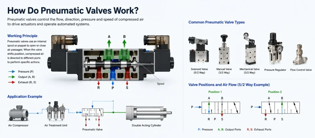
Pneumatic valves work by changing the connection between air ports inside the valve body. A typical valve may have an inlet port, outlet ports, and exhaust ports. The inlet port receives compressed air from the air supply. The outlet ports send air to actuators or tools. The exhaust ports release used air back into the atmosphere.
Inside the valve, a spool, poppet, disc, or diaphragm moves to open and close different air paths. In a spool valve, the spool slides inside the valve body. As it shifts, it connects some ports and blocks others. In a poppet valve, a sealing element lifts away from a seat to allow air to pass, then returns to the seat to stop air flow.
The position of the internal element is controlled by an actuation method. A solenoid pneumatic valve uses an electrical signal to energize a coil. This magnetic force moves a plunger or pilot mechanism, which shifts the valve. A manual pneumatic valve may use a push button, lever, or rotary knob. A mechanically actuated valve may be triggered by a roller, cam, or machine part. A pilot-operated pneumatic valve uses air pressure itself to shift the internal mechanism.
Once the valve shifts, compressed air flows through the selected passage. For example, in a cylinder circuit, air may be directed to the front side of the cylinder to extend the rod, while air from the opposite side is exhausted. When the valve shifts again, air is directed to the other side, and the cylinder retracts. This controlled switching is the foundation of pneumatic automation.
Main Components of Pneumatic Valves
Although pneumatic valves vary in size and design, most include several key components. The valve body contains the air passages and ports. The internal control element, such as a spool or poppet, determines which passages are open. Seals prevent leakage between ports. Springs may return the valve to its normal position. Actuators, such as solenoids or manual levers, shift the valve from one state to another.
Port markings are also important. Pneumatic valves commonly use standardized port labels. Port P or 1 is often the pressure supply. Ports A and B, or 2 and 4, usually connect to actuators. Ports R and S, or 3 and 5, are exhaust ports. Understanding these markings helps technicians install valves correctly and diagnose system problems faster.
| Component | Main Function | Why It Matters |
|---|---|---|
| Valve body | Contains ports and internal air passages | Determines flow capacity, pressure rating, and connection type |
| Spool or poppet | Opens and closes air paths inside the valve | Controls the direction and timing of air flow |
| Seals | Prevent air leakage between ports | Maintain efficiency and stable actuator performance |
| Spring return | Returns the valve to its normal position | Improves safety and predictable machine behavior |
| Solenoid or actuator | Moves the internal valve element | Allows electrical, manual, mechanical, or air-pilot control |
Common Types of Pneumatic Valves
There are many types of pneumatic valves, and each type is designed for a different control purpose. The most common categories include directional control valves, flow control valves, pressure control valves, shut-off valves, quick exhaust valves, and proportional valves.
Directional Control Pneumatic Valves
Directional control valves determine the path that compressed air takes. They are commonly used to control pneumatic cylinders and actuators. These valves are often described by the number of ports and positions, such as 2/2, 3/2, 5/2, or 5/3 pneumatic valves. The first number refers to the number of ports, and the second number refers to the number of valve positions.
Flow Control Pneumatic Valves
Flow control valves regulate the speed of air flow. Since actuator speed depends on how quickly air enters or leaves the actuator, flow control valves are commonly used to adjust cylinder extension and retraction speeds. A needle valve or one-way flow control valve can provide fine adjustment while allowing free flow in the opposite direction.
Pressure Control Pneumatic Valves
Pressure control valves manage air pressure in a system. A pressure regulator reduces supply pressure to a stable working pressure. A relief valve protects the system from excessive pressure. A sequence valve can trigger an operation only after a set pressure is reached. These pneumatic valves help improve safety, consistency, and equipment life.
Solenoid Pneumatic Valves
Solenoid pneumatic valves are controlled electrically. When a control system sends voltage to the solenoid coil, the valve shifts position and changes the air path. Solenoid valves are widely used in automated machines because they can be controlled by PLCs, sensors, switches, and timers.
How Directional Control Pneumatic Valves Work
Directional control is one of the most important functions of pneumatic valves. A simple 2/2 valve has two ports and two positions. It can open or close an air line, making it suitable for basic on/off control. A 3/2 valve has three ports and two positions. It is often used with single-acting cylinders, where air pushes the cylinder in one direction and a spring returns it.
A 5/2 pneumatic valve has five ports and two positions. It is commonly used with double-acting cylinders. In one position, air flows to one side of the cylinder while the other side exhausts. In the second position, the air paths reverse, causing the cylinder to move in the opposite direction. This makes 5/2 valves extremely common in industrial automation.
A 5/3 valve has five ports and three positions. The center position may be closed, exhausted, or pressurized depending on the design. These valves are useful when an actuator must stop in a controlled position, release pressure, or hold pressure under specific conditions. Choosing the correct center configuration is important because it affects machine safety and actuator behavior during stops or power loss.
The operating method also changes how the valve behaves. A single-solenoid spring-return valve returns to its normal position when power is removed. A double-solenoid valve can stay in its last position until the opposite coil is energized. This difference matters in machine design because it affects what happens during emergency stops, air loss, or electrical failure.
Flow Control and Pressure Control
Directional valves decide where air goes, but flow and pressure control valves decide how air behaves. Flow control is mainly related to speed. If air enters a cylinder too quickly, movement may be harsh, noisy, or unsafe. If air flows too slowly, production speed may suffer. By adjusting flow control pneumatic valves, operators can make movement smoother and more consistent.
Pressure control is related to force and safety. In a pneumatic cylinder, force depends on air pressure and piston area. Higher pressure creates greater force, but it can also increase wear, energy consumption, and safety risk. Pressure regulators allow users to set the correct working pressure for each part of the system. Relief valves help prevent overpressure conditions that could damage components.
In many systems, directional, flow, and pressure control pneumatic valves work together. For example, a solenoid directional valve may send air to a cylinder, a flow control valve may adjust the cylinder speed, and a regulator may ensure the cylinder receives the correct pressure. When properly designed, this combination creates accurate, repeatable, and efficient motion.
Common Applications of Pneumatic Valves
Pneumatic valves are used wherever compressed air is used for control or motion. In manufacturing, they operate cylinders that push, lift, clamp, sort, press, or transfer products. In packaging machines, pneumatic valves control sealing jaws, cutting devices, filling systems, and product handling mechanisms. In assembly lines, they control grippers, slides, rotary actuators, and indexing devices.
Pneumatic valves are also common in food processing, textile machinery, printing equipment, woodworking machines, material handling systems, and automotive production. Because compressed air is clean, widely available, and easy to control, pneumatic systems are often preferred in environments where electric motors or hydraulic oil may not be ideal.
In robotics and automation, pneumatic valves help control lightweight grippers and fast repetitive movements. In air preparation systems, valves are used with filters, regulators, and lubricators to manage air quality and pressure. In safety circuits, pneumatic valves can dump air quickly, isolate sections of the system, or return actuators to a safe state.
How to Choose Pneumatic Valves
Selecting the right pneumatic valves requires understanding the application. The first step is to identify the function. Does the system need on/off control, directional control, speed adjustment, pressure regulation, or safety exhaust? Next, consider the number of ports and positions. A single-acting cylinder may require a 3/2 valve, while a double-acting cylinder often requires a 5/2 or 5/3 valve.
Flow capacity is also critical. A valve that is too small may restrict air flow and slow actuator movement. A valve that is much larger than necessary may cost more and reduce fine control. Pressure rating, temperature range, port size, voltage, seal material, response time, and mounting style should also match the application.
The control method must fit the machine design. Manual pneumatic valves are suitable for operator-controlled equipment. Solenoid pneumatic valves are better for automated systems. Air pilot valves are useful when electrical control is not preferred or when air logic is used. In precision applications, proportional pneumatic valves may be selected because they can regulate flow or pressure continuously instead of simply switching between open and closed states.
Installation and Maintenance Tips
Pneumatic valves should be installed according to the correct flow direction, port markings, and pressure limits. Air supply should be clean and dry because dirt, moisture, and oil contamination can damage seals or cause sticking. A filter regulator is often installed upstream to improve air quality and maintain stable pressure.
Common problems with pneumatic valves include air leakage, slow response, valve sticking, coil failure, unstable pressure, and actuator movement errors. Leakage may come from worn seals, loose fittings, damaged tubing, or contamination on sealing surfaces. Slow response may be caused by undersized valves, restricted exhaust ports, low pressure, or clogged silencers.
Regular maintenance includes checking fittings, cleaning filters, draining moisture from air preparation units, inspecting tubing, confirming electrical connections, and listening for abnormal air leaks. Exhaust silencers should also be inspected because clogged silencers can restrict exhaust flow and slow down actuators. In high-cycle equipment, preventive replacement of critical pneumatic valves can reduce downtime and improve production reliability.
Conclusion
So, how do pneumatic valves work? Pneumatic valves work by opening, closing, or switching internal air passages to control the direction, pressure, and flow of compressed air. They allow machines to move cylinders, operate actuators, control tools, regulate force, and perform automated tasks with speed and repeatability.
From simple manual shut-off valves to advanced solenoid and proportional valves, pneumatic valves are central to compressed air control. The correct valve improves machine performance, reduces energy waste, protects components, and supports safer operation. By understanding valve types, port configurations, actuation methods, and maintenance requirements, engineers and technicians can build more reliable pneumatic systems and keep automated equipment running smoothly.