


Actuator Type Butterfly Valve
An actuator type butterfly valve combines a butterfly valve body with an operating mechanism that rotates the valve disc between open, closed and intermediate positions. Depending on the application, the actuator may be electric, pneumatic, hydraulic or manually operated through a gearbox.
Butterfly valves are quarter-turn valves. In most designs, approximately 90 degrees of shaft rotation moves the disc from fully closed to fully open. This relatively short travel makes butterfly valves well suited to compact actuators and automated pipeline systems.
However, selecting an actuator type butterfly valve involves more than matching an actuator to the valve mounting flange. The actuator output must be sufficient for the actual valve torque, differential pressure, disc design, seat material, operating speed and control requirement.
A large butterfly valve in a water treatment plant can require a very different actuator configuration from a smaller modulating valve used on a process skid, even when both rely on the same quarter-turn operating principle.
Select the butterfly valve according to the process conditions first, then size the actuator from the maximum realistic valve torque. Nominal valve diameter alone is not enough for reliable actuator selection.
What Is an Actuator Type Butterfly Valve?
An actuator type butterfly valve is a butterfly valve operated through an actuator connected to the valve shaft. The actuator converts electrical energy, compressed air, hydraulic pressure or manual input into rotary movement.
Inside the valve, a circular disc is positioned in the flow passage. Rotating the shaft changes the disc angle relative to the pipeline.
When the disc is approximately parallel to the flow, the valve is open. When the disc rotates across the flow path and engages the seat, the valve closes.
Intermediate disc positions can also be used for selected throttling duties when the butterfly valve design and actuator control are suitable for modulation.
Because only quarter-turn movement is required, butterfly valves can be paired with compact rotary actuators. This makes them particularly useful in large-diameter water systems, pump stations and industrial process pipelines.
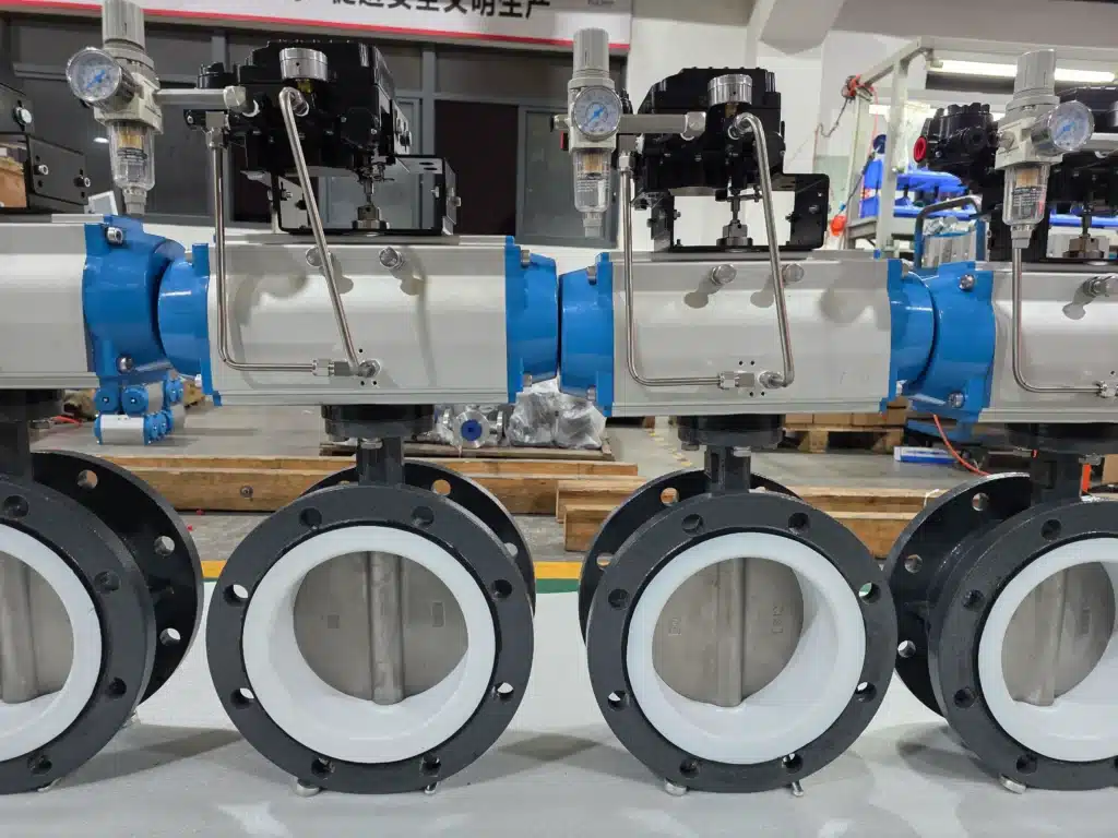
Main Butterfly Valve Actuator Types
Butterfly valve actuators can be classified according to their power source and operating principle.
| Actuator Type | Power Source | Typical Use | Main Characteristic |
|---|---|---|---|
| Elektrikli Aktüatör | Electric power | Automated industrial systems | Remote operation and convenient control integration |
| Pnömatik Aktüatör | Compressed air | Fast-cycle process systems | Fast operation and spring-return options |
| Hydraulic Actuator | Hydraulic pressure | Large or high-torque valves | High torque capability |
| Manual Gear Operator | Manual input | Occasional local operation | No external utility required |
In most automated industrial applications, electric and pneumatic actuators are the two most common choices.
Elektrikle Çalışan Kelebek Vana
An electric actuated butterfly valve uses an electric motor and internal reduction gearing to rotate the butterfly valve shaft.
Electric actuation is particularly useful where compressed air is unavailable or where the valve needs to communicate directly with a PLC, DCS or centralized electrical control system.
Depending on actuator configuration, the butterfly valve can be operated as a simple on-off isolation valve or as a modulating valve capable of holding intermediate disc positions.
On-Off Electric Actuator
An on-off electric actuator moves the butterfly valve between fully open and fully closed positions. It is commonly used for automatic isolation, pump sequencing and pipeline switching.
Modulating Electric Actuator
A modulating actuator allows the disc to stop at intermediate positions according to a control command. This configuration can be used for flow or pressure regulation when the butterfly valve itself is suitable for throttling.
Supply voltage, actuator torque, switching time, duty cycle, feedback and environmental protection should all be confirmed according to the project rather than selecting the actuator from valve size alone.
FLE60D Motorized Flanged Butterfly Valve
A motorized flanged butterfly valve designed for remote isolation and flow regulation in medium- and large-diameter industrial pipelines.
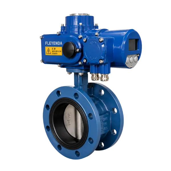
The FLE60D combines a flanged butterfly valve body with an electric actuator for remote opening, closing and regulating service. Its flanged construction provides stable pipeline alignment and makes the valve suitable for medium- and large-diameter industrial piping.
The valve is available with cast iron, WCB carbon steel and CF8 / CF8M stainless steel body options. Seat materials include EPDM, PTFE and metal, allowing the configuration to be selected according to the working medium and operating conditions.
Electric actuator options include on-off and regulating configurations, with environmental protection choices for general industrial installations, wet locations and selected hazardous-area applications.
DN40–DN1200 size range, selectable 3–10 second actuation, multiple international flange standards, IP67 / IP68 protection options and explosion-proof actuator configurations.
| Model | FLE60D | Nominal Diameter | DN40–DN1200 |
| Metric Pressure | 0.6 / 1.0 / 1.6 / 2.5 MPa | ANSI Pressure | 150LB / 300LB / 600LB / 900LB |
| JIS Pressure | 10K / 20K | Connection | Flanged Type |
| Design Standards | GB / ANSI / JIS / DIN | Actuation Time | 3–10 s |
| Body Materials | Cast Iron / WCB / CF8 / CF8M | Disc Materials | Cast Iron / Stainless Steel / WCB / Bronze |
| Seat Materials | EPDM / PTFE / Metal | Control Type | On-Off / Regulation |
| Actuator Rotation | 0°–90° or 0°–360° | Protection Options | General / IP67 / IP68 / Explosion-Proof |
| Explosion-Proof Option | Ex d II BT4 & CT6 | Application Focus | Industrial Pipeline Automation |
Pneumatic Actuated Butterfly Valve
A pneumatic actuator uses compressed air to generate rotary movement. Rack-and-pinion actuators are widely used on small and medium butterfly valves, while scotch-yoke designs can be selected for larger or more demanding torque requirements.
Pneumatic actuator butterfly valves are commonly used where rapid operation, frequent cycling and straightforward fail-safe action are required.
Accessories can include a solenoid control valve, limit switch box, air-filter regulator and valve positioner depending on the automation requirement.
For modulating service, a positioner regulates actuator air pressure so the butterfly valve follows the required control signal.
Pneumatic actuator sizing should use the minimum available instrument-air pressure at the valve, not only the nominal compressor discharge pressure.
Double-Acting vs Spring-Return Butterfly Valve Actuators
Pneumatic butterfly valve actuators are commonly available in double-acting and spring-return configurations.
Double-Acting Actuator
A double-acting actuator uses compressed air to move the valve in both directions.
Air is supplied to one side of the actuator to open the butterfly valve and to the opposite side to close it.
Double-acting actuators provide efficient torque output where a mechanical fail-open or fail-close position is not required.
Spring-Return Actuator
A spring-return actuator uses compressed air in one direction and stored spring force in the other.
If instrument air is lost, the springs move the valve toward the predetermined safe position.
The assembly can be configured as fail-close or fail-open according to the process requirement.
Fail-close is not automatically safer than fail-open. The correct fail position must be determined from the process requirement and hazard analysis.
Hydraulic Actuated Butterfly Valve
Hydraulic actuators use pressurized hydraulic fluid to generate rotary torque.
They are typically considered for very large butterfly valves or applications where high output torque is required.
Hydraulic systems can generate substantial torque from relatively compact actuator assemblies, but they require a hydraulic power source, tubing and maintenance of the hydraulic circuit.
Their use is therefore usually concentrated in applications where the additional torque capability provides a clear engineering benefit.
Manual Gear Operated Butterfly Valve
A manual gearbox is not an automated actuator, but it remains an important operating method for butterfly valves.
The gearbox increases mechanical advantage so an operator can move a larger butterfly valve using a handwheel without applying excessive force directly to the shaft.
Manual gear operators are appropriate where the valve operates infrequently and remote automation is unnecessary.
They are less suitable where valve movement must be integrated with pump interlocks, centralized control or automated process sequences.
How Butterfly Valve Design Affects Actuator Selection
The same actuator should not automatically be used for every butterfly valve of the same nominal diameter.
Butterfly valve geometry, seat construction and differential pressure all affect the torque profile.
Concentric Butterfly Valve
In a concentric butterfly valve, the shaft passes through the center of the disc and the disc remains in contact with the resilient seat during much of its rotation.
Seat friction can therefore represent a substantial part of the required operating torque.
Double-Offset Butterfly Valve
Double-offset geometry moves the disc away from the seat more quickly during opening, reducing sliding contact and making the design suitable for more demanding pressure and temperature conditions.
Triple-Offset Butterfly Valve
Triple-offset butterfly valves use additional geometric offset and a torque-seated sealing principle.
They are commonly selected for higher-temperature and severe industrial service, and their torque profile can differ significantly from a resilient-seated concentric butterfly valve.
Butterfly valve DN does not determine actuator size by itself. Valve design, seat construction, differential pressure and required operating margin must also be known.
How to Size Butterfly Valve Actuator Torque
Torque sizing is one of the most important parts of actuator type butterfly valve selection.
The actuator must generate sufficient torque throughout the complete valve travel, not only when the disc is moving freely near the middle of its stroke.
Breakaway torque, running torque and seating torque can all be different.
Important factors include differential pressure, disc diameter, seat material, butterfly valve geometry, temperature, deposits and operating frequency.
| Torque Factor | Effect on Actuator Selection |
|---|---|
| Valve Diameter | Larger discs generally require greater actuator torque |
| Differential Pressure | Higher pressure can increase hydrodynamic and seating loads |
| Seat Material | Changes friction and breakaway torque |
| Valve Design | Concentric and offset designs have different torque characteristics |
| Temperature | Can change sealing properties and operating friction |
| Deposits or Solids | Can increase torque after the valve remains stationary |
| Air Pressure | Directly affects pneumatic actuator output |
A suitable design margin is normally added to the required valve torque, but dramatically oversizing the actuator is not always beneficial.
Excessive actuator output can place unnecessary load on the shaft, disc and mechanical stops if the assembly is not correctly adjusted.
On-Off vs Modulating Actuator Type Butterfly Valve
An on-off actuator type butterfly valve operates primarily at the fully open and fully closed positions.
This configuration is appropriate for pipeline isolation where the objective is simply to permit or stop flow.
A modulating butterfly valve operates at intermediate disc angles and adjusts flow according to a control command.
However, not every butterfly valve should be treated as a precision control valve.
Valve geometry, system pressure drop and actuator resolution all affect controllability.
Oversizing can be especially problematic because normal regulation may then occur over only a narrow portion of disc travel.
For demanding modulating duty, valve Cv or Kv and the expected control range should be checked against actual process conditions.
Butterfly Valve Actuator Opening and Closing Speed
Operating speed should be selected according to the process rather than choosing the fastest actuator available.
Butterfly valves can change effective flow area rapidly because the disc requires only approximately 90 degrees of travel.
In liquid pipelines, closing a large butterfly valve too quickly can contribute to water hammer and pressure surge.
Pump systems require particular attention because valve movement, pump shutdown and check-valve behavior can interact.
Conversely, an actuator that moves too slowly can delay emergency isolation or automated process sequencing.
Actuator Type Butterfly Valve Applications
Su Arıtma
Electric and pneumatic butterfly valves are widely used for filter systems, water transfer, large pipeline isolation and automated treatment processes.
Pump Systems
Butterfly valves can isolate pump suction or discharge lines and can be integrated with automated startup and shutdown interlocks.
Closing speed should be evaluated carefully to avoid unnecessary pressure transients.
Petrol ve Doğal Gaz
Offset and severe-service butterfly valves can be automated for selected oil and gas isolation and process duties. Pressure class, sealing design and hazardous-area actuator requirements should be confirmed according to the project.
Metalurji
Butterfly valves are used in industrial water, process utilities and selected gas systems within metallurgical plants. Temperature, dust and environmental exposure influence actuator selection.
Chemical and Process Piping
Chemical compatibility should be checked for the valve body, disc, seat and shaft. PTFE-lined butterfly valves can be considered for selected corrosive media, with the actuator sized according to the resulting valve torque.
How to Select an Actuator Type Butterfly Valve
Start by defining the butterfly valve itself. Confirm pipeline size, pressure rating, medium, temperature, seat material and required valve design.
Next, determine whether the valve will be used for isolation or proportional control.
After the valve design is established, obtain the required operating torque under the maximum realistic differential pressure.
The actuator type can then be selected according to available utilities, required operating speed, fail-safe behavior and the control architecture.
| Selection Item | What to Confirm |
|---|---|
| Valve Size | DN or NPS |
| Pressure | Working pressure and maximum differential pressure |
| Medium | Water, oil, gas, chemical or other process fluid |
| Temperature | Minimum, normal and maximum operating temperature |
| Butterfly Valve Design | Concentric, double-offset or triple-offset |
| Seat Material | EPDM, NBR, PTFE, metal seat or project-specific material |
| Required Torque | Maximum valve torque under actual process conditions |
| Actuator Type | Electric, pneumatic or hydraulic |
| Control Mode | On-Off or modulating |
| Fail Position | Fail-open, fail-close or stay in position |
| Operating Speed | Required opening and closing time |
| Environment | Indoor, outdoor, wet, corrosive or hazardous area |
Common Butterfly Valve Actuator Selection Mistakes
One of the most common mistakes is choosing actuator size only from the nominal diameter of the butterfly valve.
Another is using torque data from one butterfly valve design for another valve with a different disc geometry or seat material.
Pneumatic actuators are sometimes sized using nominal compressor pressure even though actual air pressure at the valve can fall significantly during peak plant demand.
Electric actuators can also be selected incorrectly when torque is considered but duty cycle, operating speed or modulating frequency is ignored.
Another mistake is assuming every automated butterfly valve should close as fast as possible. In large liquid pipelines, excessive closing speed can contribute to hydraulic surge.
Fail-safe requirements should also be determined early in the project rather than after the actuator has already been selected.
What to Include in a Butterfly Valve Actuator RFQ
A useful RFQ should include information about both the butterfly valve and the actuator.
Provide the valve size, pressure class, body material, disc material, seat material, medium, temperature and maximum differential pressure.
State whether the butterfly valve is used for isolation or modulating control.
For an electric actuator, include available voltage, required control signal, operating time, position feedback and enclosure requirements.
For a pneumatic actuator, include minimum available air pressure, double-acting or spring-return requirement, fail position and accessory requirements.
“DN200 actuator butterfly valve” is not enough information for reliable actuator sizing. Valve design, seat material, pressure, torque, control mode and fail-safe requirements should also be provided.
Sık Sorulan Sorular
What is an actuator type butterfly valve?
It is a butterfly valve operated by an actuator such as an electric, pneumatic or hydraulic actuator instead of direct manual operation.
What type of actuator is used on a butterfly valve?
Electric and pneumatic quarter-turn actuators are the most common. Hydraulic actuators can be used where very high torque is required, while gear operators are used for manual operation.
Is an electric or pneumatic actuator better for a butterfly valve?
The appropriate choice depends on the application. Electric actuators integrate conveniently with electrical automation systems, while pneumatic actuators are useful where compressed air, fast cycling and spring-return fail-safe operation are required.
How do I size an actuator for a butterfly valve?
Obtain the valve torque requirement under maximum realistic operating conditions and select an actuator that provides sufficient output throughout the complete valve travel with an appropriate design margin.
Can a butterfly valve use a spring-return actuator?
Yes. Pneumatic spring-return actuators are commonly used when the butterfly valve must move to a predefined fail-open or fail-close position after loss of instrument air.
Can an actuator butterfly valve be used for flow control?
Yes, when the butterfly valve design and actuator are suitable for modulating service. Valve sizing and control characteristics should be checked against the required flow range and pressure drop.
Can the same actuator fit different butterfly valve sizes?
Sometimes, but compatibility depends on valve torque, shaft connection, mounting interface, travel, operating speed and safety margin. Nominal valve size alone is not sufficient.
What happens if a butterfly valve actuator is undersized?
The actuator may fail to break the valve away from the seat, stop before reaching the required position or become overloaded under maximum differential pressure.
Sonuç
An actuator type butterfly valve can use electric, pneumatic, hydraulic or manual operating mechanisms, but the correct choice depends on much more than nominal valve size.
Electric actuators are convenient for PLC and DCS automation, while pneumatic actuators provide fast operation and straightforward spring-return fail-safe configurations.
Hydraulic actuators are suitable where very high torque is required, while manual gear operators remain practical for valves that operate only occasionally.
The butterfly valve design itself is equally important. Concentric, double-offset and triple-offset valves have different seat contact and torque characteristics, so actuator sizing must use torque data for the actual valve construction.
For water treatment, pump systems, oil and gas, metallurgy and process piping, the most reliable approach is to select the butterfly valve and actuator as one engineered assembly based on pressure, temperature, valve torque, control mode, operating speed and required fail position.