| Série | AT | AW | Linear | Cilindro pneumático | Sanitário |
|---|---|---|---|---|---|
| Corpo da válvula | Válvula de esfera, válvula borboleta, válvula de obturador | Válvula de guilhotina, Válvula Global | Válvula de guilhotina | Válvula borboleta sanitária | |
| Função | Dupla ação, ação simples (FO ou FC com reajuste em caso de falha) | ||||
| Acessórios de controle | • Válvula solenóide, filtro-regulador-lubrificador (F.R.L.), posicionador, interruptor de fim de curso, volante • Solenoid Valve & Positioner are with Explosion-proof grade and Signal Feedback type for choice | ||||
| Meio de operação | Ar limpo e seco ou lubrificado, ou gás inerte. Qualquer gás não corrosivo que seja compatível com as peças internas do atuador e com o lubrificante. A temperatura do ponto de orvalho do meio de operação é de -20 °C, e o tamanho das partículas de impurezas não ultrapassa 30 u. Ao selecionar um posicionador, o tamanho das partículas de impureza não deve ser superior a 5u. | ||||
| Pressão da fonte de ar | 3 bar a 8 bar | ||||
| Temperatura do ambiente de operação | • Tipo padrão: -20 °C a +80 °C • Tipo para baixas temperaturas: -40 °C a +80 °C • Tipo para altas temperaturas: -20 °C a +160 °C | ||||
| Lubrificação | Em condições normais de operação, o modelo padrão não requer lubrificante adicional. Para ambientes de baixa ou alta temperatura, são necessários lubrificantes especiais. | ||||
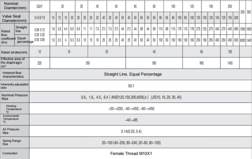
ZJHP-M Type Pneumatic Single Seat (Sleeve) Control Valve–Brief Introduction
The pneumatic control valve is one of the most widely used and critical products among the actuators in process control systems. The ZJHP type pneumatic single-seat control valve and ZJHM type pneumatic sleeve control valve, in this product series are among the universal options available to users, suitable for various fluid media and process conditions in control systems.
The ZJ series pneumatic control valves were developed through repeated expert discussions and in-depth analysis of domestic and international product characteristics, they incorporate the advantages of the latest generation of control valves globally. Leveraging mature domestic design and manufacturing expertise while considering user needs for on-site operation and maintenance, this new generation of products was designed and prototyped with distinctive Chinese features, adopting IEC international standards.
Compared to older domestic and international models, the installation height is reduced by 30%, weight is decreased by 30%, and the flow coefficient (Kv value) is increased by 30%, achieving material savings and energy efficiency. The design offers multiple flange types and connection spans, enabling the replacement of older domestic and imported products, facilitating localization and modernization.
Additionally, these valves ensure reliable operation, precise flow characteristics, a wide adjustable range, minimal seat leakage, and stable performance. The multi-spring actuator design further enhances functionality. With these unique advantages, the product delivers high-quality control performance and economic benefits across various industrial applications.
● Working principle and structure
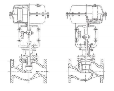
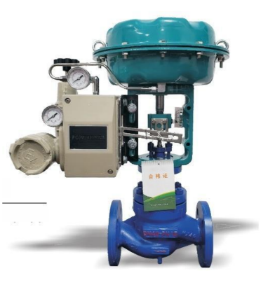
The ZJHP pneumatic single-seat control valve consists of the ZHA(B) pneumatic multi-spring diaphragm actuator and the VJP low-flow-resistance straight-through single-seat valve, as shown in Fig. 1(a).
The ZJHP-M sleeve control valve consists of the ZHA(B) pneumatic multi-spring diaphragm actuator and the VJM low-flow-resistance sleeve valve, as shown in Fig. 1(b).
When an external pneumatic signal pressure is introduced into the diaphragm chamber, this pressure acts on the diaphragm to generate thrust, which compresses the spring assembly and moves the push rod, thereby driving the valve stem to open or close the valve core until the thrust balances with the reaction force of the compressed spring assembly, stabilizing at a certain stroke. According to this principle, the stroke of the valve core forms a proportional relationship with the magnitude of the input signal pressure.
The pneumatic multi-spring diaphragm actuator can be divided into two types based on the action mode: direct-acting and reverse-acting. When the signal pressure increases, the actuator with the push rod moving outward from the diaphragm chamber is the direct-acting type, designated as the ZHA model. When the signal pressure increases, the actuator with the push rod retracting into the diaphragm chamber is the reverse-acting type, designated as the ZHB model. These are illustrated by the actuators in Fig. 1(a) and Fig. 1(b), respectively.
The ZJHP and ZJHP-M pneumatic control valves can be classified into air-to-close and air-to-open types based on their operation modes. The air-to-close valve consists of a direct-acting actuator and the valve. When the input signal pressure changes from the lower limit to the upper limit, the valve moves from fully closed to fully open. The air-to-open valve consists of a reverse-acting actuator and the valve. When the input signal pressure changes from the lower limit to the upper limit, the valve moves from fully closed to fully open. These are shown in Fig. 1(a) and Fig. 1(b), respectively.
The pneumatic multi-spring diaphragm actuator features a compact height, light weight, and simple installation and calibration. It consists of key components such as the diaphragm, compression springs, spring plate, push rod, bracket, bushing, and diaphragm cover. The diaphragm adopts a deep dish shape with minimal effective area variation and is made of high-quality rubber, ensuring normal operation within a temperature range of -40°C to +85°C. The compression springs are arranged in a multi-spring configuration to reduce height. The push rod’s guiding surface is finely machined to enhance hardness and reduce roughness, minimizing hysteresis and improving sealing. The reverse-acting actuator employs an O-ring seal, which, combined with the push rod and bushing, ensures a simple structure and reliable sealing. Through precise design and machining, this actuator eliminates the need for spring adjustment mechanisms, allowing one-time assembly and reducing adjustment efforts. The push rod and valve stem are connected via a split nut for flexible installation and removal.
The low-flow-resistance straight-through single-seat valve and sleeve valve feature a simple and compact structure with a high flow coefficient. The valve adopts a straight-through single-seat design with top-guided valve body and no bottom cover, offering compact size, light weight, and smooth flow path for high efficiency. The valve body and piping connections use raised-face or ring-joint flanges to accommodate different nominal pressures. The valve body is available in standard and high-temperature versions for different operating temperatures. The single-seat valve core is an upper-guided plunger type, while the sleeve valve core is cylindrical, guided by the inner bore of the sleeve. The sleeve is precision-machined with specially designed window openings, ensuring precise flow characteristics that comply with IEC and national standards for slope deviation requirements. The standard packing is PTFE molded packing, with flexible graphite specialty packing available for specific field requirements.
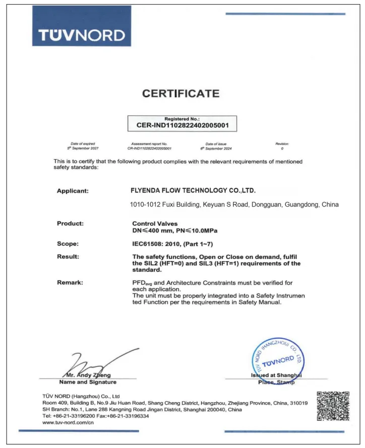
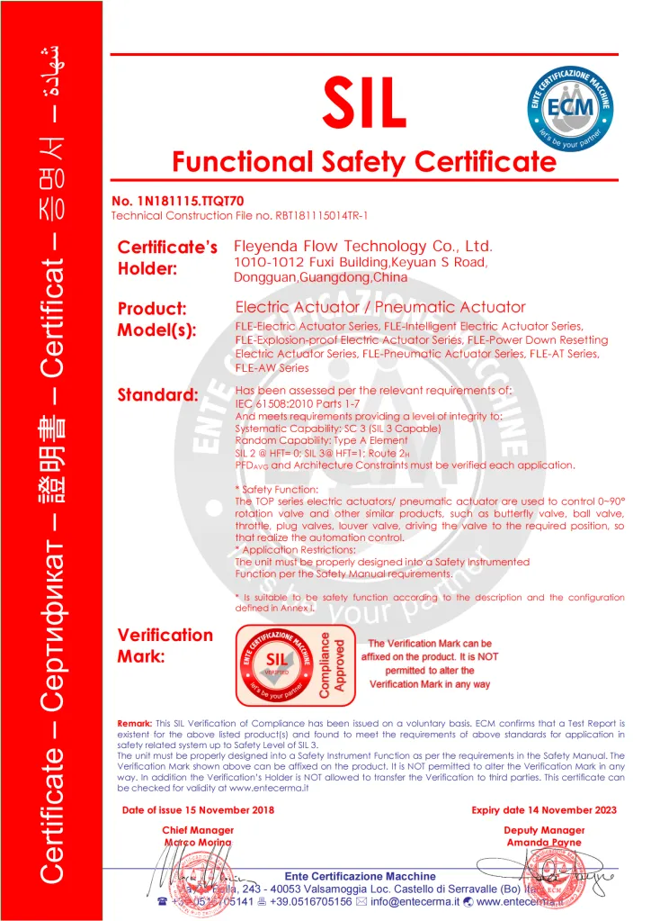
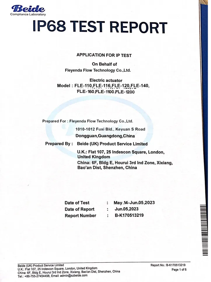
Qualidade certificada para aplicações em válvulas industriais
As válvulas e os atuadores elétricos da Fleyenda são projetados para oferecer desempenho estável, operação confiável e uso industrial de longo prazo. Com suporte de qualidade certificada, são adequados para tratamento de água, processamento químico, automação e sistemas de controle de processos industriais.