


How Does a 3-Way Motorized Ball Valve Work?
A 3-way motorized ball valve controls fluid distribution through three pipeline connections using an electrically operated rotating ball. Depending on the internal ball configuration, the valve can divert flow between two outlets, combine two incoming streams or connect selected pipeline branches.
Unlike a conventional 2-way motorized ball valve, which provides a single open or closed flow path, a 3-way design offers greater flexibility in automated piping systems. Its operation depends on the ball’s internal drilling, port orientation and electric actuator positioning.
This guide explains the operating principle of 3-way motorized ball valves, the differences between L-port and T-port designs, actuator control and the main factors engineers should consider when selecting a valve for industrial applications.
How Does a 3-Way Motorized Ball Valve Work?
A 3-way motorized ball valve consists of a valve body with three ports, an internally drilled ball, a stem and an electric actuator. The actuator rotates the ball through the stem, changing the connection between the three pipeline ports.
The operating sequence is straightforward:
- Control command: A PLC, relay or control panel sends an electrical signal to the actuator.
- Motor operation: The actuator motor and reduction gearbox generate the torque required to move the valve.
- Ball rotation: The actuator turns the stem and ball to the required angular position, commonly through a 90-degree movement.
- Flow routing: The internal ball passage aligns with the selected ports, allowing fluid to follow the required pipeline route.
The actuator determines the ball position, but the internal ball geometry determines which ports can communicate. Therefore, selecting the correct L-port or T-port configuration is essential before choosing the actuator.
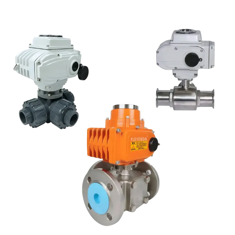
Understanding L-Port and T-Port 3-Way Ball Valves
The internal passage is the most important structural difference between the two common types of 3-way ball valves. Although both have three pipeline connections, their flow-routing capabilities are different.
L-Port 3-Way Ball Valve
An L-port ball contains an L-shaped internal passage. It is commonly used to redirect one incoming flow between two alternative outlets. By rotating the ball, the actuator selects the required branch.
For example, a pump can supply two different storage tanks through one three-way valve. In one position, the valve connects the common inlet to Tank A. After switching, the inlet connects to Tank B.
Typical applications include:
- Switching between storage tanks or process vessels.
- Changing between parallel filter or pump lines.
- Directing fluid to alternative production equipment.
- Automated pipeline changeover systems.
T-Port 3-Way Ball Valve
A T-port ball has a T-shaped internal passage that provides more flexible connections between the three ports. Depending on the drilling and ball position, it can connect different combinations of the ports, including configurations where all three ports communicate.
This arrangement can be used for selected flow distribution, bypass and mixing applications. For example, two compatible incoming streams may be connected to a common outlet, provided the valve configuration and hydraulic conditions are suitable.
Typical applications include:
- Industrial fluid distribution systems.
- Process bypass pipelines and manifolds.
- Selected mixing and flow combination arrangements.
- Automated process equipment with multiple flow paths.
It is important to note that not every T-port valve provides the same switching positions or shutoff capability. Engineers should confirm the manufacturer’s port connection diagram before specifying the valve.
| Comparison | L-Port | T-Port |
|---|---|---|
| Internal passage | L-shaped bore | T-shaped bore |
| Primary function | Flow switching and diversion | Distribution and selected mixing |
| Typical application | Tank selection, filter switching | Bypass, manifolds, process distribution |
| Flow connections | Selected two-port connections | Multiple port combinations |
| Selection priority | Required switching sequence | Required port communication in each position |
How Does the Electric Actuator Control the Valve?
The electric actuator converts electrical energy into mechanical rotation. It is responsible for moving the ball to the required position and maintaining the commanded operating state.
ON/OFF Operation
ON/OFF actuators move between predefined positions. In a 3-way valve application, the actuator’s travel limits must correspond to the intended L-port or T-port flow arrangement.
Modulating Operation
Selected electric actuators support proportional positioning through signals such as 4–20 mA or 0–10 V. This allows the control system to command intermediate positions. However, accurate flow regulation also depends on ball geometry, valve sizing, pressure differential and the flow characteristic. A standard three-way ball valve should not automatically be treated as a precision control valve.
Position Feedback and Remote Control
Position feedback allows the PLC or DCS to monitor actuator status. Depending on the selected actuator, additional options may include intelligent control, fault indication, manual override and communication functions.
When specifying an electric actuator, engineers should verify its output torque against the valve’s actual operating torque under the required pressure and service conditions.
3-Way Motorized Ball Valve vs. 2-Way Motorized Ball Valve
The main difference is the number of connections and the flow-routing function. A 2-way valve is generally selected for pipeline isolation, while a 3-way valve is designed to manage flow between three connections.
| Factor | 2-Way Motorized Ball Valve | 3-Way Motorized Ball Valve |
|---|---|---|
| Ports | Two | Three |
| Main function | Open / close isolation | Flow diversion and routing |
| Ball design | Straight-through bore | L-port or T-port |
| Typical use | Pipeline shutoff and equipment isolation | Tank switching, bypass and distribution |
| Key selection factor | Pressure, sealing and actuator torque | Port arrangement and switching logic |
If a pipeline only requires remote opening and closing, a 2-way electric ball valve is generally the simpler solution. If the process requires switching between branches or connecting multiple flow paths, a 3-way configuration may reduce the need for additional valves and pipeline connections.
Explore the complete Fleyenda electric ball valve range to compare different body constructions, connection types and actuator configurations.
Industrial Applications of 3-Way Motorized Ball Valves
Three-way motorized ball valves are used in industrial systems where automated flow routing is required. Their suitability depends on the medium, pressure, temperature, flow direction and valve construction.
Tratamento de Água e Efluentes
They can switch flow between filtration units, storage tanks, treatment stages and bypass pipelines. Automated operation helps coordinate different treatment processes without requiring manual valve operation.
Processamento Químico
In chemical production, three-way valves can direct compatible process liquids between storage vessels, reactors and production lines. The body, ball, seats and seals must be selected according to the chemical composition and operating conditions.
Petróleo e Gás
Selected three-way configurations can be used for pipeline routing, equipment switching and process distribution. Pressure ratings, sealing performance, materials and actuator protection must be verified for the specified service.
Industrial Equipment and OEM Systems
Three-way motorized ball valves are also used in packaged equipment, automated machinery and process skids where multiple fluid connections need to be controlled by a centralized electrical system.
How to Select the Right 3-Way Motorized Ball Valve
Correct selection requires matching the valve body, internal flow configuration and electric actuator to the actual process requirements.
1. Confirm the Flow Configuration
Determine whether an L-port or T-port design is required. Identify the common port, inlet, outlets and the required connections in every operating position. A simple P&ID or A/B/C port diagram can prevent incorrect valve selection.
2. Determine the Valve Size
Select the nominal diameter according to the pipeline size, required flow rate and allowable pressure loss. Nominal pipe diameter alone is not enough to establish the correct valve size.
3. Verify Pressure and Temperature
Check normal operating pressure, maximum design pressure, differential pressure and the full operating temperature range. The valve body and seat materials must remain suitable under the specified conditions.
4. Select Body and Sealing Materials
Common industrial options include CF8, CF8M, WCB, SS304 and SS316, depending on the valve series. Seat materials such as PTFE may be available for compatible applications. Material selection should consider the complete wetted assembly rather than the body alone.
5. Match Actuator Torque and Voltage
The actuator must provide sufficient torque to operate the valve under the actual differential pressure. Confirm the power supply, operating time, ON/OFF or modulating control, position feedback and any manual override requirements.
6. Define Power-Failure Requirements
Determine whether the valve should remain in its last position, move to a fail-open position or move to a fail-closed position when power is lost. These functions depend on the selected actuator configuration and should be specified before ordering.
Fleyenda 3-Way Motorized Ball Valve Products
Fleyenda provides three-way electric ball valves in different connection styles and body constructions. The following models serve distinct industrial requirements rather than representing interchangeable versions of the same valve.
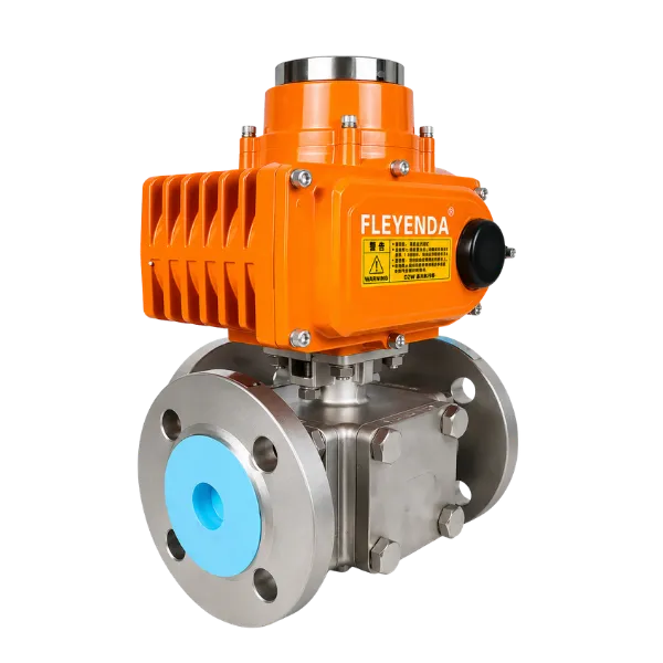
Electric 3-Way Flanged Ball Valve
Designed for fixed industrial piping systems requiring automated diversion, bypass and selected distribution or mixing functions. Available with L-port and T-port ball configurations.
| Size | DN15–DN200 |
|---|---|
| Pressão | PN10–PN40 / ANSI Class 150–300 |
| Corpo | CF8 / CF8M / WCB |
| Conexão | DIN / ANSI / JIS Flanged |
| Temperatura | −20°C to +180°C* |
3-Way Threaded High-Pressure Electric Ball Valve
This model is designed for smaller-bore threaded pipeline connections and demanding pressure applications. Its stainless-steel T/L-port construction supports automated flow switching in compatible water, oil, gas and chemical process systems.
| Size | ¼″–4″ / DN8–DN100 |
|---|---|
| Pressão | Até 1.000 PSI (6,4 MPa) |
| Corpo | SS304 / SS316 / SS316L |
| Conexão | Female NPT / BSP / BSPT |
| Temperatura | −20°C to +180°C* |
3-Way Tri-Clamp Sanitary Electric Ball Valve
Designed for hygienic process installations where rapid disassembly and cleaning are important. Its SS304 / SS316L construction, Tri-Clamp connections and cavity-filled PTFE seats support compatible food, beverage and sanitary process applications.
| Size | ½″–4″ / DN15–DN100 |
|---|---|
| Pressão | 0–10 bar (145 PSI) |
| Corpo | SS304 / SS316L |
| Conexão | Tri-Clamp / Tri-Clover |
| Temperatura | −10°C to +120°C* |
*Final pressure and temperature limits depend on the selected model, seat material and operating medium. Confirm the manufacturer’s current datasheet before ordering.
For other valve configurations, including 2-way electric ball valves, UPVC valves and PTFE-lined designs, visit the complete electric ball valve product range.
Perguntas frequentes
How does a 3-way motorized ball valve work?
An electric actuator rotates the internally drilled ball through the valve stem. The ball connects selected ports to redirect or distribute fluid according to the L-port or T-port design.
What is the difference between L-port and T-port?
L-port valves are commonly used to switch one flow path between two branches. T-port valves provide more flexible port communication and can support selected distribution and mixing arrangements.
Can a 3-way motorized ball valve mix two fluids?
Selected T-port configurations can connect two incoming streams to a common outlet. However, actual mixing performance depends on flow rates, pressure balance, valve geometry and the process design.
Can all three ports be closed simultaneously?
This depends on the ball drilling and valve construction. Some L-port designs provide an isolated position, whereas certain T-port designs maintain communication between multiple ports. Always confirm the manufacturer’s flow-position diagram.
What actuator voltage options are available?
Depending on the selected actuator, common options include DC24V, AC110V, AC220V and AC380V. Confirm the exact power supply and control circuit before ordering.
What information is required for a quotation?
Provide the valve size, port configuration, process medium, pressure, temperature, connection standard, body and seat materials, actuator voltage and required switching sequence. A piping drawing is especially useful for three-way valve selection.
Select a Suitable Motorized Ball Valve for Your Pipeline
A 3-way motorized ball valve provides automated flow routing when its internal ball design matches the required pipeline arrangement. Understanding L-port and T-port configurations helps engineers select the correct valve body, actuator and switching sequence.
Fleyenda offers electric ball valve solutions for industrial isolation, diversion and flow routing, including flanged, threaded and sanitary configurations.
Explore the Fleyenda electric ball valve range or send your process requirements for technical assistance.