


3 Way Valve Control Valve Guide
A 3 way valve is an important component in industrial fluid control systems where two flow streams need to be mixed or one stream needs to be diverted between different pipelines. Compared with a conventional two-way control valve, a three-way control valve provides an additional flow path for process regulation, temperature control and fluid distribution. This guide explains the working principle of a 3 way control valve, its mixing and diverting configurations, pneumatic diaphragm actuation, material options and industrial applications, helping engineers and equipment manufacturers select the right control valve for their process requirements.
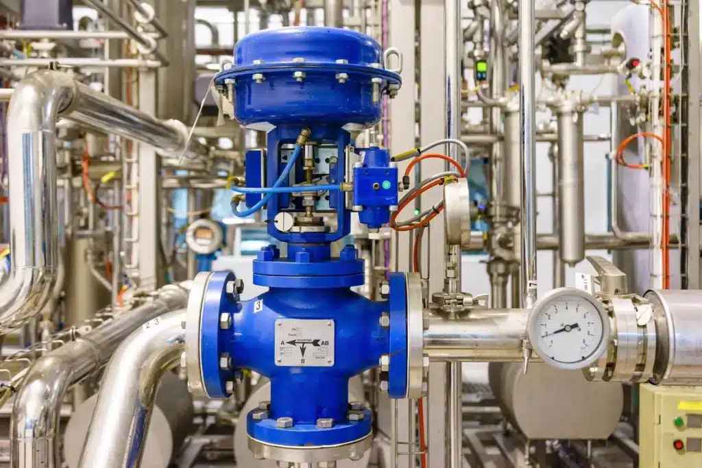
What Makes a 3 Way Control Valve Different?
A three-way control valve uses three pipeline ports to manage the relationship between two fluid streams or two outlet circuits.
Three-Port DesignConnects three pipeline branches for mixing or diverting service.
Flow RegulationAdjusts flow distribution according to process control requirements.
Pneumatic ActuationUses diaphragm actuators for controlled valve movement.
Aplicações industriaisSuitable for compatible steam, water, oil and chemical process systems.
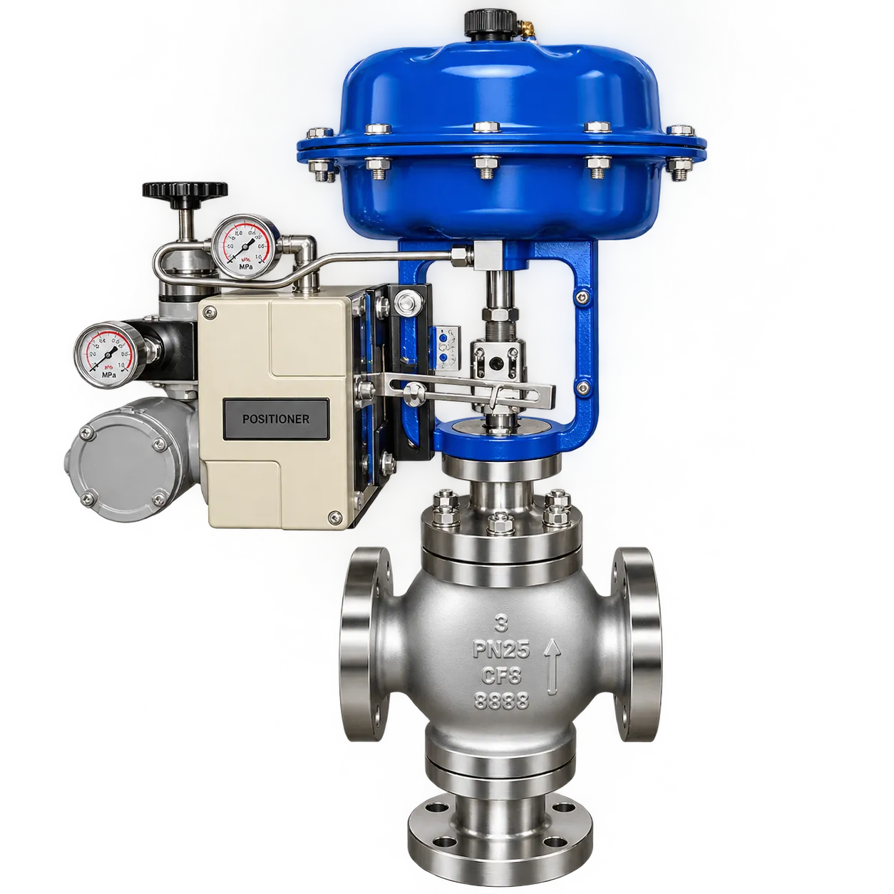
F-ZJHQ 3-Way Pneumatic Diaphragm Control Valve
The F-ZJHQ is a three-way pneumatic diaphragm control valve designed for industrial mixing and diverting applications. Its three-port valve body, pneumatic diaphragm actuator and configurable material options provide a solution for process lines requiring controlled fluid distribution and regulation.
Nominal Size
Working Pressure
Working Temperature
Material da carroceria
Mixing and Diverting Control
Three-port flow arrangements support combining two inlet streams or distributing one inlet stream between two outlet paths.
Pneumatic Diaphragm Actuator
Available with single-acting or double-acting actuator configurations and a positioner for process regulation.
Multiple Material Options
Carbon steel, SS304 and SS316 body options, with PTFE or EPDM diaphragm selections.
Flexible Pipeline Connections
Flanged, threaded and welded connection options can be configured according to project requirements.
The F-ZJHQ 3-way control valve is suitable for compatible industrial process applications involving steam, water, air, oil and chemical solutions. Valve configuration should be confirmed according to the process medium, flow direction, pressure, temperature and required control characteristics.
1. What Is a 3 Way Control Valve?
A 3 way control valve is an industrial valve designed with three flow ports to regulate fluid movement between connected pipelines. It can operate in either a mixing or diverting configuration, depending on its internal construction and piping arrangement.
Unlike a standard two-way control valve, which primarily regulates flow through one inlet and one outlet, a three-way valve provides an additional connection for managing two fluid streams or two separate flow paths.
A typical three-way control valve consists of:
- Three-way valve body: Contains three ports and the internal flow passages.
- Valve trim: Controls the opening area and flow distribution inside the valve.
- Valve stem: Transfers actuator movement to the internal regulating components.
- Diaphragm actuator: Converts pneumatic pressure into mechanical movement.
- Positioner: Adjusts actuator air pressure to achieve the required valve position.
Three-way control valves are commonly installed in industrial pipelines where process fluids need to be combined, separated or redirected. They are particularly useful in heating systems, boiler plants, thermal power generation, petrochemical facilities and other process industries.
3 Way Control Valve vs. 3 Way Ball Valve
It is important to distinguish between a three-way control valve and a three-way ball valve. Although both have three flow connections, their operating mechanisms and primary functions are different.
A three-way ball valve typically uses a rotating ball with an L-port or T-port passage to switch between flow paths. A pneumatic diaphragm control valve uses a regulating mechanism and actuator to adjust flow according to a control signal.
For applications requiring continuous process regulation, temperature control or controlled mixing, a properly sized three-way control valve is generally the more appropriate solution.
2. How Does a 3 Way Valve Work?
The working principle of a 3 way valve depends on how its three ports are arranged. The two main configurations are mixing control and diverting control.
Mixing 3 Way Valve
A mixing control valve combines two separate inlet streams into one common outlet. Fluid enters through ports A and B, while the mixed fluid exits through port AB.
CONTROL VALVE
Combined Outlet
A + B → AB
The valve adjusts the relative flow contribution from the two inlet streams. This arrangement is commonly used in heating circuits, water temperature regulation and industrial liquid blending systems.
For example, a heating system may combine hot water from a boiler with cooler return water to achieve a required supply temperature. A three-way control valve adjusts the flow distribution according to the temperature control system.
Diverting 3 Way Valve
A diverting control valve operates in the opposite direction. One common inlet stream enters through port AB and is distributed between two separate outlets, A and B.
CONTROL VALVE
AB → A + B
By changing the valve position, the flow distribution between the two outlet branches can be regulated. This configuration is useful in process systems where a fluid needs to be distributed between alternative circuits or equipment.
Mixing and diverting functions are not automatically interchangeable. The valve body construction, internal trim, port designation and installation direction must match the intended application.
3. Mixing vs. Diverting 3 Way Control Valves
Choosing between mixing and diverting configurations is one of the most important steps when selecting a three-way control valve.
| Comparação | Mixing Valve | Diverting Valve |
|---|---|---|
| Flow Direction | Two inlets to one outlet | One inlet to two outlets |
| Port Arrangement | A + B → AB | AB → A + B |
| Função principal | Combines two fluid streams | Distributes one fluid stream |
| Aplicações típicas | Temperature adjustment, fluid blending | Flow distribution, circuit switching |
| Selection Priority | Inlet conditions and mixing requirements | Outlet flow requirements and branch conditions |
Before ordering a 3 way valve, engineers should provide a simple pipeline diagram showing the inlet, outlet and required flow direction. This helps the manufacturer confirm the correct valve configuration and avoid incorrect installation.
4. 3 Way Control Valve vs. 2 Way Control Valve
Both two-way and three-way control valves are used in industrial flow regulation, but they serve different purposes.
A two-way control valve regulates flow through a single inlet and outlet. A three-way control valve manages two connected flow paths, allowing mixing or diverting operations.
| Item | 2 Way Control Valve | 3 Way Control Valve |
|---|---|---|
| Number of Ports | 2 | 3 |
| Flow Function | Regulates one flow path | Mixing or diverting |
| Temperature Control | Controls flow to equipment | Can mix hot and cold streams |
| Pipeline Design | Generally simpler | Requires three-port connections |
| Uso típico | Flow isolation and regulation | Fluid blending and distribution |
A three-way control valve can simplify certain piping arrangements by combining two flow paths into one valve assembly. However, it is not automatically a replacement for two independent two-way valves. The process requirements, pressure conditions, control strategy and operating modes must be evaluated before choosing the configuration.
5. How Does a Pneumatic Diaphragm Control Valve Work?
A pneumatic diaphragm control valve uses compressed air to move the valve stem and adjust the internal regulating element. In a three-way control valve, this movement changes the opening of the internal flow passages and controls the distribution between the three ports.
Main Components of a Pneumatic Diaphragm Actuator
- Diaphragm: Converts pneumatic pressure into mechanical force.
- Spring assembly: Provides the opposing force in applicable single-acting configurations.
- Actuator stem: Transfers movement to the valve regulating mechanism.
- Positioner: Compares the commanded position with actual movement and adjusts actuator air pressure.
- Air supply system: Provides clean compressed air for actuator operation.
Operating Process
For applications requiring more accurate control, a valve positioner is an important accessory. It helps maintain the commanded valve position despite changes in friction, differential pressure and actuator operating conditions.
Single-Acting vs. Double-Acting Actuators
| Item | Single-Acting | Double-Acting |
|---|---|---|
| Operating Force | Air pressure and spring force | Air pressure in both directions |
| Return Mechanism | Retorno da primavera | Opposite pneumatic pressure |
| Failure Position | Can be configured for fail-open or fail-closed | Depends on the actuator and additional failure-control arrangement |
| Selection | Applications requiring a defined spring-return action | Applications requiring pneumatic operation in both directions |
The F-ZJHQ actuator configurations include single-acting and double-acting options. Fail-open (FO) and fail-closed (FC) requirements should be confirmed during engineering selection, together with the actual valve port arrangement and process safety requirements.
6. Industrial Applications of 3 Way Control Valves
Three-way control valves are used in industrial systems where process fluids must be blended, distributed or regulated between different equipment and pipeline branches.
Boiler Plants and Steam Systems
In boiler facilities, three-way control valves can be applied in compatible water, condensate and auxiliary process circuits. Mixing configurations may help adjust fluid temperature, while diverting configurations can distribute flow between different equipment branches.
Thermal Power Generation
Thermal power plants use extensive networks of steam, water and auxiliary fluid pipelines. A three-way control valve can provide mixing or diverting functions in selected utility and process circuits, subject to the pressure, temperature and material requirements of each service.
Petrochemical and Refining
Petrochemical facilities handle different liquid and gaseous process media through complex pipeline systems. Three-way control valves can be used for compatible fluid blending, process flow routing and temperature regulation. Body and diaphragm materials must be selected according to the chemical composition and operating conditions.
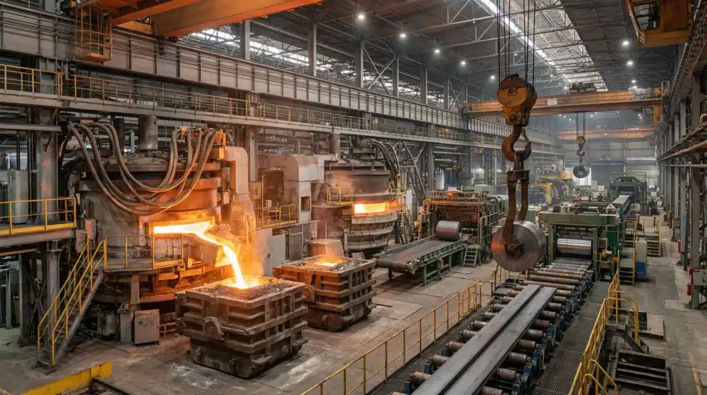
Metallurgy and Heavy Industry
Metallurgical plants use industrial water, oil and auxiliary process fluids in production equipment, cooling systems and hydraulic circuits. Three-way valves can help distribute or mix fluids between connected equipment and process lines.
Industrial Heating and Cooling Systems
Heating and cooling circuits often require temperature adjustment by combining supply and return fluids. A mixing three-way control valve can regulate the relative contribution of hot and cooler streams to achieve the required supply conditions.
7. Valve Body and Diaphragm Material Selection
Material selection is an important part of choosing a 3 way control valve. The valve body and diaphragm must withstand the process medium, working pressure, temperature and chemical exposure.
Carbon Steel Valve Body
Carbon steel is commonly considered for compatible industrial water, steam, oil and general process services where the operating environment does not require the additional corrosion resistance of stainless steel.
SS304 Stainless Steel
SS304 provides corrosion resistance for many general industrial applications. It may be selected for compatible water, air and process-fluid systems where the chemical environment and temperature are suitable.
SS316 Stainless Steel
SS316 provides improved resistance to certain corrosive environments compared with SS304. It is often considered for more demanding chemical and process-fluid applications. Actual compatibility should be confirmed according to fluid concentration and temperature.
PTFE and EPDM Diaphragms
The diaphragm is an important sealing and actuation component. PTFE and EPDM options offer different chemical and temperature compatibility characteristics.
| Componente | Available Material | Considerações sobre a seleção |
|---|---|---|
| Corpo da válvula | Aço carbono | General process conditions and corrosion requirements |
| Corpo da válvula | SS304 | Compatible water and general industrial media |
| Corpo da válvula | SS316 | More demanding corrosion environments |
| Diaphragm | PTFE | Chemical compatibility and temperature conditions |
| Diaphragm | EPDM | Compatible water-based and other specified process media |
Final material selection should be based on the complete operating conditions rather than the valve body material alone. The diaphragm, internal trim, seals and connection components should also be reviewed.
8. F-ZJHQ 3 Way Pneumatic Control Valve Technical Specifications
The F-ZJHQ three-way pneumatic diaphragm control valve is available in different sizes, pressure ratings, body materials and actuator configurations to support industrial project requirements.
| Model | F-ZJHQ |
|---|---|
| Tipo de válvula | 3-Way Pneumatic Diaphragm Control Valve |
| Nominal Size | DN15–DN300 (½″–12″) |
| Working Pressure | 0.6–6.4 MPa (6–64 bar) |
| Working Temperature | -20°C to +220°C |
| Material da carroceria | Carbon Steel / SS304 / SS316 |
| Diaphragm Material | PTFE / EPDM |
| Flow Configuration | Mixing / Diverting |
| Tipo de conexão | Flanged / Threaded / Welded |
| Applicable Medium | Steam, Water, Air, Oil, Corrosive Fluids and Chemical Solutions |
| Actuator Type | Pneumatic Diaphragm Actuator with Positioner |
| Actuator Function | Single-Acting / Double-Acting |
| Failure Position | Fail Open / Fail Closed Options |
| Air Supply Pressure | 3–8 bar |
| Acessórios de controle | Positioner, Solenoid Valve, F.R.L., Limit Switch, Handwheel |
| Design References | GB/T 12238, IEC 534, ANSI B16.34, DIN EN 1349 |
| Testing References | GB/T 13927, API 598, EN 12266-1 |
| Certification References | CE / RoHS / ISO 9001; IP65 actuator protection as listed |
| Personalização | Special materials, parameters and configurations available according to project requirements |
Allowable pressure and temperature must be verified for the selected valve size, body material, internal components and operating conditions. Design and testing references should also be confirmed against the project specification.
9. How to Select the Right 3 Way Control Valve
Correctly selecting a three-way control valve requires more than matching the valve size to the pipeline diameter. Engineers should evaluate the process flow, operating conditions, control requirements and actuator configuration.
1. Confirm Mixing or Diverting Requirements
Determine whether the process requires two streams to be combined or one stream to be distributed between two outlets. Confirm the A, B and AB port arrangement with the manufacturer.
2. Identify the Process Medium
Provide the fluid name, composition, concentration, viscosity and any special characteristics. These details influence the selection of valve body and diaphragm materials.
3. Determine the Required Flow Capacity
Valve sizing should be based on minimum, normal and maximum flow rates, inlet and outlet pressures, fluid properties and required control performance. The flow coefficient (Cv or Kv) should be calculated for the actual operating conditions. Nominal pipe diameter alone is not sufficient to determine the correct control valve size.
4. Confirm Pressure and Temperature
Specify normal operating conditions as well as maximum and minimum design conditions. For steam and high-temperature services, check the pressure-temperature limits of the complete valve assembly.
5. Select the Valve Body and Diaphragm
Choose carbon steel, SS304 or SS316 according to the process medium and corrosion requirements. Confirm PTFE or EPDM diaphragm compatibility with the fluid and operating temperature.
6. Select the Actuator Configuration
Specify single-acting or double-acting pneumatic actuation. Confirm the required fail-open or fail-closed position and whether a positioner, solenoid valve, F.R.L. or limit switch is required.
7. Confirm the Pipeline Connection
Choose flanged, threaded or welded connections according to the existing pipeline, pressure rating and project standard.
Providing these details allows the control valve manufacturer to evaluate the complete configuration and recommend a suitable three-way valve for the application.
10. Installation and Maintenance Considerations
Correct installation is essential for the performance and service life of a 3 way control valve. Incorrect flow direction, actuator configuration or pneumatic supply conditions can affect the control system.
Verify Flow Direction and Port Connections
Confirm the valve body markings, A/B/AB port identification and intended mixing or diverting configuration before connecting the pipelines. Do not assume that all three-way valve bodies can be installed in either direction.
Check Pneumatic Air Supply
Use clean and dry or otherwise compatible instrument air according to actuator requirements. The F-ZJHQ actuator reference lists an air supply pressure range of 3–8 bar. Confirm that the available supply pressure is suitable for the selected actuator and positioner.
Inspect the Positioner and Accessories
Check the positioner, solenoid valve, filter regulator and feedback accessories during commissioning. Confirm that the control signal produces the correct valve movement.
Test Failure Behavior
Where fail-open or fail-closed operation is required, verify the actual valve position after loss of air supply or control signal. The failure behavior must be checked against the actuator configuration and the complete process safety strategy.
Schedule Regular Inspection
Inspect the diaphragm, sealing components, actuator connections, valve stem and pneumatic accessories according to operating frequency and process conditions. Early detection of leakage, unstable movement or actuator response problems helps reduce unplanned downtime.
Frequently Asked Questions About 3 Way Control Valves
What is a 3 way valve used for?
A 3 way valve is used to combine two fluid streams into one outlet or distribute one inlet stream between two outlet paths. In industrial control systems, it supports mixing, diverting, temperature regulation and fluid distribution.
What is the difference between a 3 way valve and a 3 way control valve?
A three-way valve describes the general three-port valve configuration. A three-way control valve is specifically designed for regulating flow between its ports, commonly using a pneumatic or electric actuator and an appropriate control system.
What is the difference between mixing and diverting valves?
A mixing valve combines two inlet streams into one common outlet (A + B → AB). A diverting valve takes one common inlet stream and distributes it between two outlet paths (AB → A + B). The correct valve construction must match the required flow direction.
How does a pneumatic diaphragm control valve work?
A pneumatic diaphragm control valve uses compressed air to move a diaphragm and actuator stem. The positioner adjusts actuator air pressure according to the control signal, allowing the valve to regulate the process flow.
What materials are available for the F-ZJHQ 3 way control valve?
The F-ZJHQ product information lists carbon steel, SS304 and SS316 valve body options, together with PTFE and EPDM diaphragm choices. The final material combination should be selected according to the process medium and operating conditions.
What is the size and pressure range of the F-ZJHQ control valve?
The listed nominal size range is DN15–DN300, with a working pressure range of 0.6–6.4 MPa. The allowable pressure should be confirmed for the selected size, material and temperature.
Can a 3 way pneumatic control valve be equipped with a positioner?
Yes. The F-ZJHQ configuration includes a pneumatic diaphragm actuator with a positioner. Additional accessories such as solenoid valves, F.R.L. units, limit switches and handwheels can be selected according to project requirements.
What information is required when ordering a 3 way control valve?
Provide the nominal size, working pressure, temperature, process medium, flow arrangement, body and diaphragm materials, connection type, actuator function and required accessories. A pipeline diagram showing the three port connections is also useful for technical confirmation.
Looking for a Reliable 3 Way Control Valve for Your Industrial Project?
Fleyenda supplies pneumatic diaphragm control valves for industrial flow regulation, mixing and diverting applications. The F-ZJHQ series offers multiple body materials, diaphragm options, connection configurations and actuator functions for different process requirements.
Send us your process medium, pipeline size, operating pressure, temperature and flow diagram. Our team can help evaluate the appropriate 3 way control valve configuration for your project.
Email: inquiry@fleyendaflow.com