


Electric Actuated Ball Valves for Oil & Gas Applications: Selection, Automation & Safety
Electric actuated ball valves are widely used in oil and gas facilities where automated isolation, remote pipeline operation and reliable process control are required. From production equipment and pipeline stations to refinery utility systems, the right electric ball valve helps improve operating efficiency while reducing dependence on manual valve operation.
Selecting electric actuated ball valves for oil and gas applications requires more than matching the nominal pipe size. Engineers must evaluate operating pressure, temperature, process media, sealing materials, actuator torque, hazardous-area classification and control requirements. This guide explains where motorized ball valves are used across the oil and gas industry, how to select the right configuration, and which Fleyenda products may suit different industrial duties.
For a broader overview of available configurations, explore our electric ball valve product range.
Recommended Electric Actuated Ball Valves for Oil & Gas Applications
Fleyenda offers electric actuated ball valves for industrial pipeline isolation, high-pressure auxiliary systems and process flow regulation. Select the appropriate valve construction according to your operating conditions.
FLE-Q-F Electric 2-Way Flanged Ball Valve
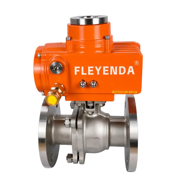
Designed for automated isolation in industrial pipelines, the FLE-Q-F combines a flanged ball valve body with an electric quarter-turn actuator for remote opening and closing.
FLE-Q-G High Pressure 2-Way Threaded Electric Ball Valve

The FLE-Q-G is a compact high-pressure electric ball valve for small-bore industrial piping and equipment systems. Its stainless-steel construction supports selected high-pressure applications.
FLE-VQ-F Electric V-Port Segmented Ball Valve
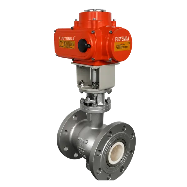
The FLE-VQ-F features a characterized V-port ball design for progressive flow adjustment. It is suitable for selected oil and gas process applications requiring more than simple pipeline isolation.
*Technical specifications depend on valve size, seat material, process medium and actuator configuration. Confirm final operating limits with the product datasheet.
Explore the complete Fleyenda Electric Ball Valve Range.
Where Are Electric Actuated Ball Valves Used in the Oil & Gas Industry?
Oil and gas operations cover several stages, from exploration and production to transportation, storage, refining and petrochemical manufacturing. Each stage has different process conditions and valve requirements. Electric actuated ball valves are commonly considered where remote isolation, automated switching or integration with plant control systems is needed.
1. Upstream: Oil and Gas Production Facilities
Upstream operations include production facilities, gas gathering systems, separation equipment, water treatment packages and utility networks. These installations often include remote or unmanned areas where manual valve operation can increase maintenance workload and delay routine process changes.
Electric actuated ball valves can be used on compatible auxiliary process lines, equipment skids, utility services and selected production-support systems. The valve body, seats and actuator must be checked against the actual pressure, temperature, fluid composition and hazardous-area classification.
For wellhead, Christmas tree and other high-pressure well-control duties, specify valves designed and qualified for the applicable API 6A requirements. A general-purpose industrial electric ball valve should not be assumed suitable for wellhead service.
2. Midstream: Pipelines, Pump Stations and Storage Terminals
Midstream facilities transport and store crude oil, refined products and natural gas. Pipeline stations, tank farms, compressor stations and pump skids rely on dependable valve operation to isolate equipment, switch process routes and support maintenance activities.
Electric actuated ball valves can provide remote isolation for compatible station piping, auxiliary services, equipment connections and selected transfer systems. Flanged configurations are often practical for permanent industrial piping where the project defines ANSI, DIN or JIS connections.
For mainline transmission and pipeline block-valve duties, the complete valve must meet the applicable pipeline design, pressure, fire-safe, testing and project requirements. Confirm API 6D applicability, size, class, materials, end connections, actuator duty and documentation before specifying a product.
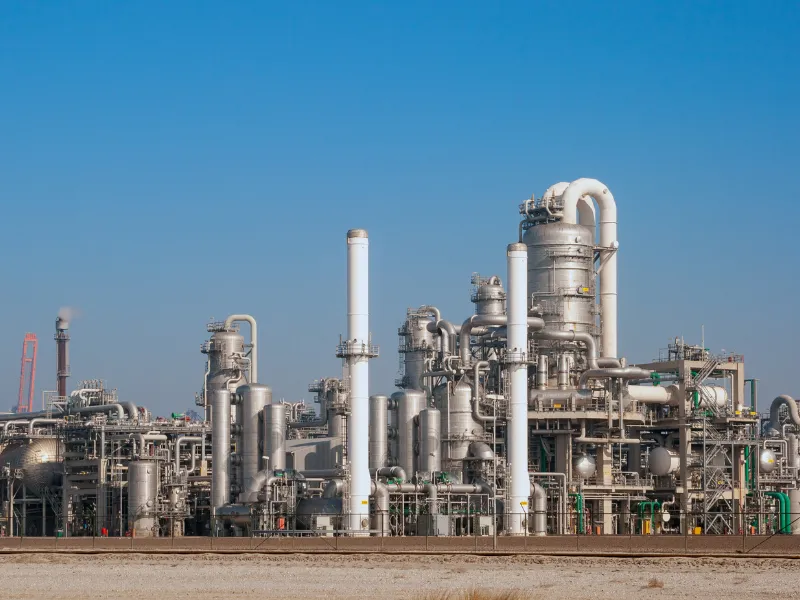
3. Downstream: Refineries and Petrochemical Plants
Downstream facilities process crude oil into fuels, lubricants and petrochemical feedstocks. Their piping systems handle a wide range of hydrocarbons, process fluids, steam, cooling water and chemical additives.
Electric actuated ball valves can be used for compatible equipment isolation, transfer lines, utility piping, tank connections and automated process switching. Stainless-steel or carbon-steel body options and suitable seat materials should be selected according to the fluid composition and operating envelope.
Where the process requires continuous flow adjustment, a V-port electric ball valve or a dedicated control valve may be more appropriate than a standard full-bore on/off ball valve.
4. Tank Farms and Loading Systems
Storage terminals use automated valves to isolate tanks, control transfer routes and coordinate loading or unloading operations. Electric actuation can reduce routine manual intervention and provide valve-position feedback to a centralized control room.
For these duties, confirm the required shutoff function, operating frequency, actuator speed, feedback contacts, local controls and the action required during power loss. The complete system should be designed around the facility’s operating and emergency procedures.
How Electric Actuated Ball Valves Improve Oil & Gas Pipeline Automation
An electric actuated ball valve combines a ball valve body with an electric quarter-turn actuator. When the actuator receives an electrical command, its motor and gearbox generate torque to rotate the valve stem and ball. The movement changes the flow path between open, closed or a specified intermediate position when the actuator and valve are configured for modulation.
In an oil and gas facility, the actuator may receive commands from a local control station, PLC or DCS. Depending on the selected control circuit, limit switches or position feedback can report valve status to the automation system.
Control CommandPLC, DCS or local station sends an operating command.
Electric ActuationThe motor and gearbox generate the required torque.
Valve MovementThe actuator rotates the stem and ball to the commanded position.
Status FeedbackPosition signals or limit switches report valve status.
For a more detailed explanation of actuator components and operation, read our guide to how an actuator valve works. For broader industrial applications, see the Guide des vannes motorisées.
ON/OFF Control vs. Modulating Control
Not every electric actuated ball valve is designed for continuous throttling. The control mode must match the process function.
| Facteur de sélection | ON/OFF Ball Valve | Modulating Ball Valve |
|---|---|---|
| Fonction principale | Isolation entièrement ouverte ou entièrement fermée | Adjusts flow through intermediate positions |
| Typical Command | Open / close signal | Selected 4–20 mA or compatible positioning signal |
| Common Application | Pipeline isolation and equipment switching | Feed-flow, dosing and process regulation |
| Valve Configuration | Standard round-port ball | V-port or suitable control-valve design |
For applications requiring repeatable proportional control, the FLE-VQ-F V-port ball valve provides 15°, 30°, 60° and 90° opening options, with selected modulating actuator configurations. Its final size and V-port geometry should be determined from the required Cv, flow range and pressure drop.
Electric vs. Pneumatic Actuated Ball Valves in Oil & Gas Facilities
Electric and pneumatic actuators are both used in oil and gas automation. The correct choice depends on the available energy source, operating frequency, response time, control accuracy, hazardous-area requirements and required failure behavior.
| Comparaison | Actionneur électrique | Actionneur pneumatique |
|---|---|---|
| Power Source | Electrical supply | Compressed instrument air |
| Installation | Useful where electrical power is available but compressed air is not | Requires a suitable air supply and distribution system |
| Position Control | Selected models support positioning and modulation | Positioning is available with a compatible positioner |
| Operating Speed | Depends on actuator torque and configuration | Often suitable for fast cycling |
| Power Failure | Must be specified; standard models do not automatically return to a safe position | Spring-return designs can provide defined fail-open or fail-closed action |
| Typical Selection | Remote operation and selected modulation | Frequent operation and pneumatic fail-safe options |
Electric actuators are often practical for remote stations, packaged equipment and facilities without an established compressed-air network. Pneumatic actuators may be preferable where rapid cycling or a spring-return action is required and reliable instrument air is available.
Neither technology should be selected by general preference alone. Compare the actual operating duty and safety requirements. Read our detailed electric vs. pneumatic ball valve comparison before finalizing the actuator type.
Explosion-Proof Electric Actuated Ball Valves for Hazardous Oil & Gas Areas
Oil and gas facilities may contain flammable gases or vapors around production equipment, gas processing units, tank farms, loading areas and refinery process systems. Electrical equipment installed in classified hazardous areas must be suitable for the area’s classification and the substances that may be present.
Selected Fleyenda electric actuator configurations offer Ex d II BT4 / CT4 / CT6 Gb options. The required protection marking must be confirmed against the project hazardous-area classification, gas group, temperature class, ambient conditions and applicable certification requirements.
Key Requirements for Hazardous-Area Selection
- Area classification: Confirm the applicable Zone or Division and equipment protection requirements.
- Gas group: Verify that the actuator marking is suitable for the gases or vapors present.
- Temperature class: Check the maximum surface-temperature requirement for the classified location.
- Ingress protection: Specify the required IP rating for outdoor exposure, moisture and dust.
- Electrical accessories: Check cable glands, wiring interfaces, junction boxes and local controls.
- Documentation: Request the applicable certificates for the exact actuator model and ordered configuration.
Explosion-proof protection and fire-safe valve construction are different requirements. An explosion-proof actuator does not automatically make the complete valve assembly fire-safe. Where fire-safe performance is specified, confirm the valve design and applicable test documentation separately.
ESD, Fail-Safe Operation and Power-Loss Requirements
Emergency shutdown (ESD) systems are used to move equipment into a defined safe condition when a process reaches a hazardous or abnormal state. In oil and gas facilities, the required action may include isolating a line, stopping transfer or protecting downstream equipment.
A standard electric actuated ball valve should not automatically be considered an ESD valve. The actuator’s behavior during power failure, the required response time, the safety logic, feedback, reliability targets and complete shutdown architecture must be specified and verified.
What Should Be Defined Before Ordering?
- Required final position: fail-open, fail-closed or remain-in-place.
- Power-loss behavior and whether stored electrical energy or another fail-safe mechanism is required.
- Required opening or closing time under the actual valve torque.
- Control-system interface, shutdown command and position feedback.
- Required safety integrity level (SIL), if applicable to the safety instrumented function.
- Proof-test, inspection and maintenance requirements for the complete assembly.
Fail-safe behavior is configuration-specific. It must be confirmed in the actuator datasheet and project documentation rather than assumed from the term “electric actuated ball valve”.
How to Select Electric Actuated Ball Valves for Oil & Gas Applications
Reliable selection starts with the process conditions. A valve that matches the nominal pipe diameter may still be unsuitable if its pressure rating, seat material, actuator torque or hazardous-area protection does not match the actual duty.
1. Identify the Process Medium
Specify whether the valve will handle crude oil, natural gas, refined products, produced water, condensate, steam, compressed air or chemical additives. For mixed or corrosive media, provide the composition, concentration, contaminants and any suspended solids. Material compatibility must be checked for the body, ball, stem, seat and seals.
2. Vérifier la pression et la température
Provide normal operating pressure, maximum operating pressure, design pressure, differential pressure and any surge or transient conditions. Temperature must be evaluated together with pressure because the allowable pressure rating can change with temperature and seat material.
3. Select Body and Seat Materials
Stainless steel 304 or 316 and carbon steel WCB are available on selected Fleyenda valve configurations. Seat options vary by model and may include PTFE, Nylon, PPL or selected metal-seat designs. The correct material depends on the medium, corrosion exposure, temperature, pressure and sealing requirements.
For sour-service environments containing H₂S, review the applicable NACE MR0175 / ISO 15156 requirements and obtain confirmation that the actual materials, hardness, manufacturing controls and documentation meet the project specification. Do not assume that a standard stainless-steel designation alone establishes sour-service compliance.
4. Choose the Correct Valve Configuration
Standard 2-way ball valves are generally used for open-close isolation. Three-way valves are selected for diverting or mixing flow paths. V-port segmented ball valves are considered when proportional flow control is required. The valve geometry should match the process function before the actuator is selected.
5. Confirm Valve Size and Connection
Specify nominal diameter, flange standard, pressure class, face-to-face dimension and end connection. For threaded high-pressure valves, confirm NPT, BSP or BSPT requirements because these thread forms are not interchangeable. For permanent industrial piping, flanged construction may provide a more suitable installation and maintenance arrangement.
6. Calculate the Required Actuator Torque
Actuator torque must be based on the valve’s operating torque under actual differential pressure, temperature, seat material and process conditions. It should include an appropriate engineering safety margin. Selecting an actuator only by valve diameter can result in incomplete travel, overload trips or unnecessary oversizing.
7. Define Voltage and Control Mode
Confirm the electrical supply, such as DC24V, AC110V, AC220V or AC380V where supported by the selected actuator. Specify whether the valve requires open-close operation, position feedback, 4–20 mA modulation or intelligent control. Check compatibility with the site’s PLC, DCS or SCADA architecture.
8. Specify Environmental and Safety Requirements
Confirm ambient temperature, outdoor exposure, IP protection, hazardous-area classification, cable entry, manual override and power-loss behavior. For safety-related applications, define the required fail position, response time, feedback and verification documentation before placing the order.
| Engineering Parameter | Information to Provide |
|---|---|
| Process Medium | Fluid or gas composition, concentration and corrosiveness |
| Operating Conditions | Normal / maximum pressure, differential pressure and temperature |
| Valve Specification | DN, pressure class, body, ball, stem and seat materials |
| Connexion | ANSI / DIN / JIS flange or NPT / BSP / BSPT thread |
| Actionneur | Required torque, voltage, operating time and duty cycle |
| Contrôle | ON/OFF, 4–20 mA, feedback and PLC / DCS interface |
| Safety | IP rating, Ex marking, fail position and ESD requirements |
| Project Documents | Datasheet, drawings, test reports and applicable certificates |
For more information about actuator sizing, operating conditions and common technical problems, see our guide to electric actuated ball valve failures and troubleshooting.
Important API and Industry Standards for Oil & Gas Valve Selection
Oil and gas projects often define valve design, inspection, fire testing, materials and hazardous-area requirements through project specifications and recognized industry standards. The applicable standards depend on the valve type, service, installation location and contractual requirements.
| Standard | Scope / Selection Relevance |
|---|---|
| API 6D | Pipeline and piping valves. Relevant where the project specifies pipeline-valve design and qualification. |
| API 608 | Metal ball valves for petroleum and natural gas industries. |
| API 598 | Valve inspection and pressure testing requirements. |
| API 607 | Fire testing requirements for applicable quarter-turn valves and related configurations. |
| API 6A | Wellhead and Christmas tree equipment; relevant to specified upstream well-control applications. |
| NACE MR0175 / ISO 15156 | Material selection for environments containing H₂S in oil and gas production. |
| IEC 60079 | Electrical equipment protection for explosive atmospheres and hazardous-area installations. |
Fleyenda product pages list different design references and testing options according to the valve series. For example, selected FLE-Q-F configurations list API 6D as a design reference, API 598 testing and selected API 607 fire-safe options. These references must not be interpreted as a blanket certification for every size or actuator combination.
Before procurement, confirm the exact standard edition, test scope, certificate type, product configuration and required inspection documents with the supplier and project engineering team.
Installation and Maintenance of Electric Actuated Ball Valves
Correct installation and regular inspection help maintain reliable valve operation in oil and gas facilities. A properly selected valve can still experience premature failure if the pipeline is misaligned, the actuator is incorrectly wired or the operating conditions exceed the specified limits.
- Check pipeline alignment: Avoid excessive external loads on the valve body and flange connections.
- Verify actuator mounting: Confirm the mounting interface, stem coupling and installation orientation.
- Inspect electrical connections: Check supply voltage, grounding, cable glands and control wiring.
- Test valve travel: Verify fully open and fully closed positions, travel limits and feedback signals.
- Monitor operating torque: Investigate abnormal noise, slow movement, overload alarms or incomplete travel.
- Review sealing performance: Inspect for external leakage and confirm shutoff performance under approved test conditions.
- Maintain safety accessories: Inspect manual overrides, position indicators and specified fail-safe components.
Maintenance intervals should be determined by the service severity, operating frequency, manufacturer recommendations and site maintenance program. If a valve repeatedly fails to operate, identify the electrical, mechanical and process-related causes rather than simply increasing the actuator torque setting.
Oil & Gas Valve Automation Experience
Fleyenda has supplied valve automation solutions for demanding oil and gas applications. One documented project involved an upstream oil and gas facility in Malaysia, where the supplied package included electric actuated valves, pneumatic actuated valves, precision globe control valves and customized actuators.
The project addressed high pressure, corrosive media and remote installation conditions. Its automation requirements included reducing manual intervention, supporting remote valve operation, improving process response and simplifying maintenance. The project documentation also describes corrosion-resistant materials, remote monitoring capabilities and ATEX-certified components within the supplied package.
This project demonstrates experience in broader oil and gas valve automation. The exact valve models, actuator configurations and certifications must still be matched to each new project’s specifications.
Read the Oil & Gas Actuated Valve Solutions Case Study →
Explore additional oil and gas valve solutions for upstream, midstream and downstream applications.
Electric Actuated Ball Valves for Oil & Gas: FAQs
1. What are electric actuated ball valves used for in the oil and gas industry?
Electric actuated ball valves are used for automated isolation, remote shutoff, equipment sequencing and selected flow-control duties in oil and gas facilities. Typical applications include compatible process lines, utility systems, pump skids, storage terminals and refinery equipment. The valve must be selected according to its pressure, temperature, medium and project requirements.
2. Can electric actuated ball valves be used in oil and gas pipelines?
Yes, selected electric actuated ball valves can be used in compatible pipeline and station applications, particularly for equipment isolation, utility piping and process systems. Mainline transmission duties require a complete valve assembly that meets the applicable pipeline standards, pressure class, size, fire-safe and project qualification requirements. A general-purpose industrial ball valve should not automatically be treated as an API 6D-qualified pipeline valve.
3. Are explosion-proof electric ball valves required in oil and gas facilities?
Where the installation is classified as a hazardous area, the electrical actuator and associated accessories must meet the applicable protection requirements. The required Ex marking depends on the area classification, gas group, temperature class and project regulations. Not every oil and gas installation has the same hazardous-area requirements.
4. What is the difference between electric and pneumatic ball valves for oil and gas?
Electric ball valves use an electric motor and gearbox, while pneumatic ball valves use compressed air to generate actuator movement. Electric actuators can simplify remote control where electrical power is available. Pneumatic actuators are often suitable for fast cycling and spring-return fail-safe duties where a reliable instrument-air supply is available. The required failure behavior should guide the selection.
5. Can an electric actuated ball valve perform emergency shutdown (ESD)?
Only a properly engineered and qualified valve-actuator package should be used for a specified ESD function. A standard electric actuator does not automatically provide fail-safe operation during power loss. Confirm the required fail position, response time, safety integrity requirements, control architecture and applicable documentation before selection.
6. Which materials are suitable for oil, gas and sour-service applications?
Material selection depends on the fluid composition, pressure, temperature, corrosion exposure and sealing requirements. Stainless steel and carbon steel are available on selected Fleyenda configurations. For sour service containing H₂S, confirm compliance with the applicable NACE MR0175 / ISO 15156 requirements through material specifications and project documentation.
7. What information is needed to request a quotation?
Provide the medium, pipe size, normal and maximum pressure, differential pressure, operating temperature, valve material, connection standard, actuator voltage, control mode, hazardous-area classification and required certificates. For modulating service, also provide minimum, normal and maximum flow rates and pressure-drop data.
8. Does Fleyenda offer electric ball valves with PLC or DCS integration?
Selected actuator configurations support remote open-close commands, position feedback, 4–20 mA regulating signals and intelligent control options. The required interface should be specified with the actuator model, voltage, wiring arrangement and control-system requirements.
Looking for Electric Actuated Ball Valves for Your Oil & Gas Project?
Share your pipeline conditions and technical requirements with Fleyenda. Our team can help review valve construction, pressure rating, body and seat materials, actuator torque, control mode and hazardous-area options for your application.
Email: inquiry@fleyendaflow.com