


Wie schnell sollte sich ein motorbetriebenes Kugelventil öffnen und schließen?
A motorized ball valve can complete its opening or closing stroke in a few seconds or take considerably longer, but faster operation is not automatically better. The correct switching time depends on the piping system, flow velocity, pipe length, valve size, pump sequence, process medium and the consequences of changing flow too quickly.
In industrial automation, valve speed affects more than production efficiency. A motorized ball valve that closes too quickly on a liquid line can produce a sudden change in fluid momentum and contribute to pressure surge or water hammer. A valve that operates too slowly can create a different problem by delaying isolation, disrupting pump sequencing or extending the time required to redirect process flow.
This is why selectable switching time can be more useful than simply specifying a “fast motorized ball valve.” Fleyenda motorized valve configurations can provide selectable opening and closing times in the 3–10 second range, allowing valve response to be matched more closely to the actual process.
Switching speed is also only one part of actuator selection. Environmental protection, behavior after power loss and hazardous-area requirements can be equally important. IP68 protection, power-failure reset and explosion-proof actuator configurations can therefore become key factors when the valve is installed outdoors, around pumps, in wet treatment plants or in oil and gas facilities.
The best motorized ball valve opening time is not the shortest available time. The objective is to select a stroke time that provides the required process response without creating unnecessary hydraulic or mechanical stress.
What Determines Motorized Ball Valve Speed?
The operating time of a motorized ball valve is primarily determined by the electric actuator. Most industrial ball valves use quarter-turn movement, so the actuator normally rotates the valve stem approximately 90 degrees between fully open and fully closed positions.
The time required to complete that rotation depends on motor speed, gearbox ratio, actuator torque capacity, electrical design and control logic. A faster gear ratio can reduce operating time, but it can also change the available output torque and mechanical loading on the drivetrain.
Valve torque also affects real operating performance. A large flanged ball valve operating at high differential pressure can require substantially more torque than a small valve handling clean water at low pressure. Seat material, temperature, deposits and long periods without cycling can further increase the force required to start movement.
For this reason, the specified motorized ball valve opening time should always be considered together with actuator torque rather than treated as an independent parameter.
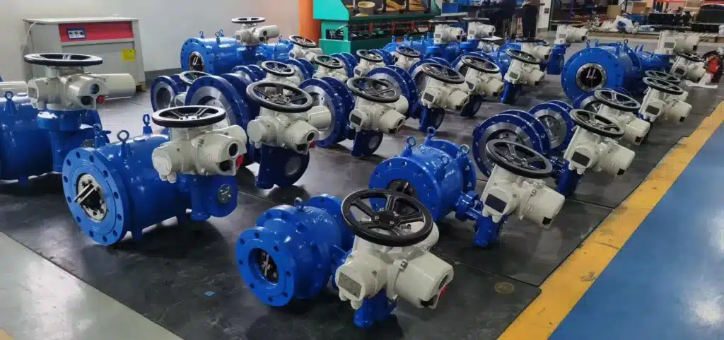
Why Faster Is Not Always Better
A common assumption in industrial automation is that a faster actuator provides better process performance. In reality, the ideal valve speed depends on what happens to the process fluid when the flow path changes.
If a motorized ball valve is installed on a short low-volume line, rapid operation may cause little hydraulic disturbance and can improve machine or skid response. The same three-second closing time on a long water pipeline with high fluid velocity may generate a much stronger pressure transient.
Faster movement also means that the mechanical components accelerate and stop more rapidly. The actuator coupling, stem, ball and seats must therefore tolerate the resulting load over the expected number of cycles.
Slower operation is not automatically safer either. A valve that takes too long to close may be unsuitable for a process that requires rapid isolation. A slow three-way valve can also leave a pump or process line in an undesirable transitional flow condition for longer than necessary.
The correct engineering question is therefore not “How fast can this motorized ball valve move?” but “How fast should it move in this system?”
What Does a 3–10s Switching Time Mean?
A selectable 3–10 second switching range provides the ability to match the motorized ball valve response to different operating conditions instead of using one fixed actuator speed for every project.
A three-second setting can be useful where fast flow switching is required and the hydraulic system can tolerate rapid movement. Intermediate settings can provide a balance between process response and pressure stability, while a longer setting approaching ten seconds may be preferable where sudden changes in liquid velocity should be reduced.
These values should not be treated as universal rules. Pipe diameter, line length, liquid velocity, system pressure, pump characteristics and valve location all influence the transient response.
| Switching Requirement | Engineering Consideration |
|---|---|
| Fast response | A shorter stroke time may be useful for equipment sequencing or rapid process switching. |
| General automatic isolation | An intermediate stroke time can provide a practical balance between response and stability. |
| Liquid line with surge concern | A slower setting may help reduce the rate of flow change. |
| Three-way flow diversion | Speed should be coordinated with pump and downstream flow requirements. |
On critical high-flow systems, switching-time selection should be supported by hydraulic or transient analysis rather than by using a fixed rule based only on valve diameter.
Opening Time vs Closing Time
Opening and closing do not always create the same hydraulic effect. Closing a liquid valve reduces the available flow area and decelerates the moving fluid. If that deceleration occurs rapidly, pressure can rise sharply upstream of the valve.
Opening a valve rapidly can also produce a transient. A sudden increase in flow may cause pressure to drop, accelerate fluid rapidly and change the operating point of a connected pump.
For this reason, some systems benefit from different opening and closing characteristics. A valve may need to open relatively quickly during startup while closing more gradually during normal shutdown.
When evaluating a fast acting motorized ball valve, engineers should therefore check whether the published switching time applies equally in both directions and whether the actuator allows speed adjustment according to the process sequence.
Motorized Ball Valve Speed and Water Hammer
Water hammer occurs when fluid velocity changes rapidly enough to generate a pressure wave through the piping system. A rapidly closing motorized ball valve can be one of several possible causes.
The severity of the pressure transient depends on fluid velocity, pipe length, pipe elasticity, wave speed, system geometry and the relationship between valve closing time and hydraulic response.
This is particularly important because a ball valve changes flow area nonlinearly as it rotates. The final portion of valve travel can produce a significant change in effective flow area even though only a relatively small amount of angular movement remains.
Selecting a longer closing time can help in some systems, but simply slowing the actuator does not guarantee that water hammer will disappear. Pump check valves, air pockets, pipeline profile, control sequence and other equipment can also create surge events.
For large pump stations, long transmission lines or high-velocity water systems, do not select valve closing time from a general 3–10 second rule alone. A transient analysis may be required.
Selecting Motorized Ball Valve Speed for Pump Systems
Pump systems are one of the applications where motorized ball valve speed has a direct relationship with system operation.
During pump startup, the control sequence may require a valve to reach a defined position before the pump is energized. During shutdown, the valve and pump may need to operate in a coordinated sequence to avoid reverse flow, excessive pressure fluctuation or deadheading.
A valve that moves too slowly can extend startup time or delay isolation. A valve that closes too quickly can create an abrupt reduction in discharge flow.
For pump skids and packaged pumping systems, actuator switching time should therefore be treated as part of the complete control sequence rather than simply as a valve specification.
Position feedback is also valuable because the PLC can confirm that the motorized ball valve has reached the required position before changing pump status.
Speed in a Motorized 3 Way Ball Valve
Switching time becomes particularly important when a motorized 3 way ball valve is used to redirect process flow between multiple pipelines.
Depending on whether the valve uses a T-port or L-port ball, actuator rotation changes the communication between the three connected ports. During this movement, the system temporarily passes through intermediate flow conditions.
In a pump system, moving too quickly can suddenly transfer discharge from one branch to another. Moving too slowly can leave the flow path partially restricted or maintain an intermediate connection longer than intended.
The selected switching time should therefore be coordinated with the required port sequence, pump behavior and downstream process requirements.
Fleyenda Electric Flanged 3 Way Ball Valve
The Fleyenda Electric Flanged 3 Way Ball Valve combines a three-port flanged ball valve with electric actuation for automated diversion, mixing and flow-direction control. It can be configured around T-port or L-port flow requirements for industrial pipeline systems.
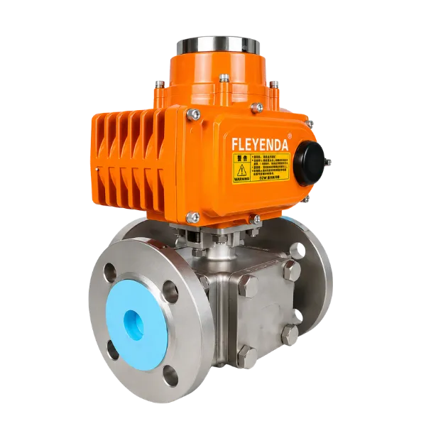
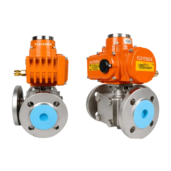
This type of motorized ball valve is particularly suitable where one automated valve needs to redirect or combine flow between three pipeline connections. Flanged construction is suitable for industrial piping, while electric actuation allows remote control and integration with plant automation.
| Ventiltyp | Electric flanged 3 way ball valve |
| Größenauswahl | DN15–DN200 |
| Port Configuration | T-port or L-port |
| GB Pressure Options | PN16 / PN25 |
| ANSI Pressure Options | Class 150 / 300 / 600 |
| Karosserieoptionen | Carbon steel and stainless steel configurations |
| Seat Options | PTFE, nylon, PPL or hard alloy depending on service |
| Actuator Control | On/off or intelligent electric actuator configurations |
For applications requiring faster process response, selected Fleyenda actuator configurations can provide 3–10 second switching options. IP68 protection, power-failure reset and explosion-proof configurations can also be selected according to project and site requirements.
How Torque Affects Motorized Ball Valve Switching Time
Opening time cannot be separated from torque. The actuator must generate sufficient torque to break the ball away from the seats, rotate it through the stroke and reseat it at the opposite end.
Valve torque is influenced by differential pressure, seat material, valve size, temperature, media condition and the time the valve remains stationary.
A high-speed actuator with insufficient torque is not a better solution than a slower actuator that can reliably complete the stroke under maximum operating conditions.
Larger flanged motorized ball valves, metal-seated valves and valves handling high differential pressure can require significantly more actuator output than small soft-seated valves.
Actuator selection should therefore compare the actual valve torque requirement with available actuator torque across the complete operating range.
Power-Failure Reset and Safe Valve Position
Switching speed is only useful when the actuator can respond correctly to abnormal operating conditions. A power failure can leave a standard electric actuator wherever it happened to stop unless the system includes a defined fail-safe strategy.
A motorized ball valve with power-failure reset can be configured to return toward a predetermined safe position after loss of normal electrical power, depending on the selected actuator configuration and control philosophy.
The correct safe position is application dependent. A chemical feed line may need to close, while a cooling or circulation line may require a different response.
This function should therefore be specified together with required valve position, available backup energy and control logic rather than simply described as “fail safe.”
Why IP68 Matters for a Motorized Ball Valve
Motorized ball valves are frequently installed in locations where the actuator is exposed to water, humidity, rain, washdown or temporary flooding.
In these environments, enclosure protection directly affects long-term electrical reliability. Water entering the actuator can damage the motor, limit switches, control board, wiring terminals and position sensors.
An IP68 motorized ball valve actuator provides a higher level of protection than the more common IP67 configuration and can be useful for demanding outdoor and wet industrial environments.
Water treatment facilities, pump stations and outdoor process skids are typical locations where enclosure protection deserves the same attention as valve pressure rating.
Final suitability should still consider cable glands, wiring connections, installation orientation and the actual immersion or environmental conditions defined for the project.
Explosion-Proof Motorized Ball Valves
Oil and gas, petrochemical and selected chemical processes may locate motorized valves in classified hazardous areas where ordinary electrical equipment is not acceptable.
In these applications, the electric actuator can be supplied in an explosion-proof configuration appropriate to the required project classification and certified model.
The actuator rating must be checked against the hazardous-area requirements, gas group, temperature class and protection concept specified by the project.
Explosion-proof selection should not be based on the appearance of the actuator enclosure. Certification documents and the actual actuator nameplate should be verified before installation.
This requirement is independent of switching speed. A three-second actuator that does not meet the site electrical classification is not suitable simply because its mechanical performance is adequate.
On-Off vs Modulating Motorized Ball Valve Operation
Switching time is most straightforward for an on-off motorized ball valve because the actuator repeatedly moves between defined open and closed positions.
A modulating motorized ball valve operates differently. Instead of completing every command as one full 90-degree stroke, the actuator may stop repeatedly at intermediate positions according to a control signal.
In this case, positioning accuracy, duty cycle, motor heating and valve flow characteristic can become more important than the full-stroke time alone.
Standard round-port ball valves also have nonlinear flow characteristics, so accurate regulation may require a V-port ball valve or another valve specifically designed for control service.
Choosing Motorized Ball Valve Speed by Application
Wasseraufbereitung
Motorized ball valves can be used for automatic isolation, tank transfer, filter sequencing and process-water routing. Rapid operation can improve process response, but high-flow liquid lines should be checked for pressure surge before selecting the shortest available closing time.
Pumpensysteme und Pumpenmodule
Pump systems require valve operation to be coordinated with startup and shutdown logic. Selectable 3–10 second switching can help match valve travel to the pump sequence rather than forcing the control system to work around a fixed actuator speed.
Öl und Gas
Oil and gas applications may require rapid isolation, but switching time must be evaluated together with pipeline pressure, medium compressibility, actuator torque and hazardous-area requirements. Explosion-proof actuator configuration can be an essential part of the package.
Metallurgie
Metallurgical facilities use automated valves in cooling water, process utilities, gas systems and equipment skids. Dust, moisture and harsh plant conditions can make actuator enclosure protection particularly important.
Commissioning and Stroke-Time Testing
The specified motorized ball valve opening time should be verified after installation because actual field performance can differ from factory expectations.
Supply voltage, valve torque, control settings and process pressure can affect the observed stroke.
During commissioning, operators should measure the time from the control command to confirmed final valve position. Limit-switch feedback should be checked against the actual mechanical position of the ball.
Pump startup and shutdown should then be tested with the valve in the real sequence to determine whether pressure remains stable.
If the actuator provides selectable 3–10 second operation, the final setting should be recorded in the commissioning documentation so later maintenance does not unintentionally alter the hydraulic behavior of the system.
How to Select a Motorized Ball Valve
Motorized ball valve selection should begin with the process conditions rather than the actuator speed.
First define the medium, valve size, operating pressure, maximum differential pressure and temperature. Then determine whether the valve is used for isolation, diversion, mixing or modulation.
After selecting the valve body, ball, seat materials and port arrangement, actuator torque can be calculated. Only then should switching time, control signal, fail-safe behavior and enclosure protection be finalized.
| Selection Item | What to Confirm | Why It Matters |
|---|---|---|
| Valve Function | Isolation, diversion, mixing or control | Determines valve and port configuration |
| Valve Size | Required nominal diameter | Affects flow capacity and torque |
| Pressure | Operating and differential pressure | Affects valve load and actuator sizing |
| Temperature | Minimum and maximum process temperature | Affects seat and seal selection |
| Seat Material | PTFE, PPL, nylon, metal or another option | Affects torque, temperature and sealing |
| Actuator Torque | Output above maximum valve torque requirement | Ensures reliable full travel |
| Switching Time | Required opening and closing speed | Affects response and hydraulic transient |
| Steuerung | On-off or intelligent/modulating | Determines actuator electronics |
| Power Failure | Required safe position | Defines fail-safe strategy |
| Ingress Protection | Environmental exposure and IP requirement | Protects actuator electronics |
| Hazardous Area | Applicable certified classification | Determines explosion-proof requirement |
Common Motorized Ball Valve Selection Mistakes
Choosing the fastest available actuator without evaluating the piping system is one of the most common mistakes. High speed can be useful, but unnecessary speed can increase pressure surge and mechanical loading.
Another mistake is selecting actuator torque from valve diameter alone. Actual torque changes with pressure, seat material, temperature and process condition.
Buyers also sometimes specify an IP rating but overlook cable entries and field wiring. The complete installed actuator assembly must maintain the required environmental protection.
A similar issue occurs with explosion-proof equipment. The hazardous-area certification must match the actual project requirements rather than simply being described as “Ex-proof.”
Finally, a power-failure reset function should not be ordered without defining what position is actually safe for the process.
What to Include in a Motorized Ball Valve RFQ
A useful motorized ball valve RFQ should provide enough information to select the valve body and electric actuator as one complete assembly.
Specify the medium, valve size, pressure, differential pressure, temperature, valve material, seat material, flange standard and required port arrangement.
For the actuator, specify supply voltage, on-off or intelligent control, required switching time, position feedback and duty requirements.
If selectable 3–10 second operation is required, state the preferred opening and closing time or explain the process objective so the final setting can be confirmed during commissioning.
Environmental requirements should include IP protection, outdoor or wet installation conditions, power-failure reset requirements and hazardous-area classification where applicable.
“Motorized ball valve DN100” is not enough information for a reliable quotation. Valve torque, actuator speed, control method and site conditions are all part of the final automated valve package.
Frequently Asked Questions About Motorized Ball Valve Speed
How fast should a motorized ball valve open?
There is no universal opening time. The correct speed depends on required process response, valve size, system pressure, flow rate and the behavior of connected pumps or equipment.
How fast should a motorized ball valve close?
Closing time should be fast enough to meet isolation requirements but slow enough to avoid unacceptable hydraulic transients. Liquid systems require particular attention to water hammer.
Is a 3-second motorized ball valve too fast?
Not necessarily. Three-second operation can be suitable for some systems, but it should not be assumed safe for every high-flow liquid pipeline.
Why would I choose a 10-second closing time?
A longer closing time can reduce the rate at which flow changes and may be useful where pressure surge is a concern. The complete hydraulic system still needs to be considered.
Can motorized ball valve speed be adjusted?
Some actuator configurations provide selectable switching times. Fleyenda configurations can provide 3–10 second options depending on the selected actuator model and project requirement.
Can a fast motorized ball valve cause water hammer?
Yes. Rapid closure can contribute to water hammer in liquid systems because it causes a rapid change in fluid velocity. Pipe length, velocity, pressure and other system components also influence the transient.
What is an IP68 motorized ball valve?
It refers to a motorized valve assembly using an actuator enclosure designed for the applicable IP68 ingress-protection requirement. This can be useful in demanding wet or outdoor environments.
What happens to a motorized ball valve when power fails?
A standard actuator may stop when power is lost. A configuration with a power-failure reset function can be designed to move toward a predefined safe position according to the selected system.
Can a motorized ball valve be explosion-proof?
Yes. Explosion-proof electric actuator configurations are available for selected hazardous-area applications. The actual certification must match the project area classification.
Can a motorized 3 way ball valve use T-port and L-port configurations?
Yes. Three-way ball valves can use different internal port arrangements. T-port and L-port designs provide different flow-routing functions and should be selected from the required process flow diagram.
Fazit
The ideal motorized ball valve opening and closing time is not simply the fastest speed available. Switching time must match the hydraulic behavior, process sequence and safety requirements of the system.
Selectable 3–10 second operation provides flexibility because the same basic valve automation concept can be adapted to different response requirements. Faster settings can support rapid process switching, while slower settings may be more appropriate where abrupt flow changes need to be reduced.
Switching speed must also be considered together with actuator torque. A fast actuator is useful only if it can reliably move the valve under maximum differential pressure and actual operating conditions.
Environmental and safety functions are equally important. IP68 protection can improve suitability for demanding wet environments, power-failure reset can support a defined safe-state strategy, and explosion-proof configurations can address hazardous-area requirements when correctly certified for the project.
For water treatment, pump systems, oil and gas, metallurgy and other industrial applications, the best motorized ball valve is therefore not the one with the shortest stroke time. It is the valve and actuator package whose speed, torque, protection and control behavior match the real process.