


INDUSTRIAL FLOW CONTROL GUIDE
Control Valve: Types, Working Principle, Sizing & Industrial Selection
A control valve is a critical component in industrial process automation. It regulates the flow of liquids, gases or steam to maintain process variables such as pressure, temperature, flow rate and liquid level. Selecting the right control valve requires more than matching the valve size to the pipeline. Engineers must also consider flow characteristics, pressure drop, valve materials, actuator performance and actual operating conditions.
This guide explains how industrial control valves work, compares common valve designs, and outlines practical methods for sizing and selecting control valves for water treatment, chemical processing, oil and gas, metallurgy and other industrial applications.
What Is a Control Valve?
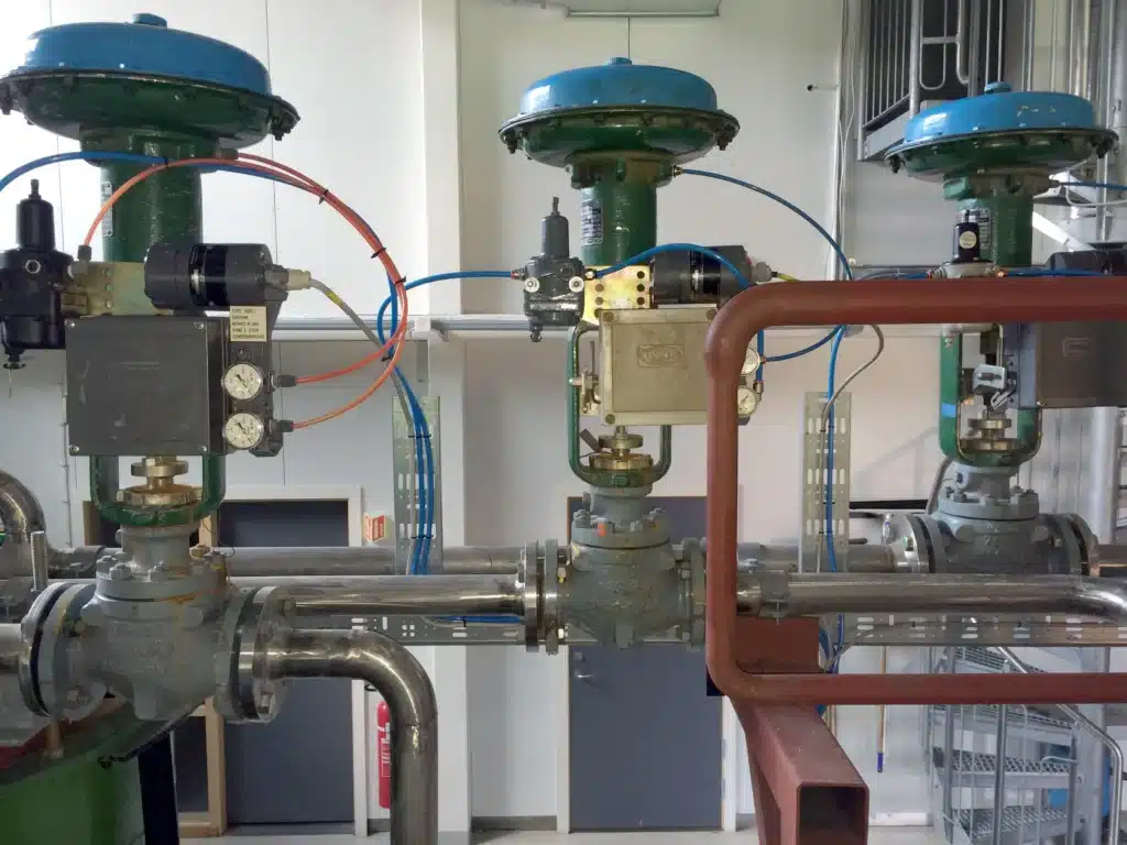
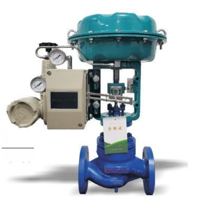
An industrial control valve is a final control element that adjusts fluid flow in response to a command from a process controller. It is commonly used in closed-loop systems to maintain a target flow rate, pressure, temperature or liquid level.
Unlike a basic isolation valve, which is primarily intended to stop or allow flow, a modulating control valve can operate at intermediate positions. By changing the opening between the closure element and the valve seat or body, it changes the hydraulic or pneumatic resistance of the process line.
A complete control valve assembly may include a valve body, trim, actuator, positioner, position feedback device and associated control accessories. The exact configuration depends on the required process function and automation architecture.
How Does a Control Valve Work?
- Measure the process variable. A flow meter, pressure transmitter, temperature sensor or level instrument measures the current process condition.
- Compare the measurement with the setpoint. A PLC, DCS or dedicated controller determines whether the process variable needs to increase or decrease.
- Send a control command. The controller transmits a suitable signal to the valve actuator or positioner.
- Adjust the valve opening. The actuator moves the closure element to change the effective flow area.
- Verify and correct. Position feedback and process measurements help the automation system maintain the required operating condition.
For example, when downstream pressure falls below its target, a control system may open a suitable valve to increase flow. The actual response depends on the process configuration, controller logic and valve action.
Control Valve vs. On-Off Valve: What Is the Difference?
One of the most important purchasing decisions is determining whether the application requires continuous regulation or simple isolation. An automated valve is not automatically a control valve simply because it has an electric or pneumatic actuator.
| Comparison | Control Valve | On-Off Valve |
|---|---|---|
| Primary function | Regulates flow or another process variable | Starts, stops or switches flow |
| Operating positions | Intermediate positions within its designed range | Normally fully open or fully closed |
| Control method | Modulating signal and suitable positioning system | Open and close commands |
| Key sizing factors | Cv/Kv, flow characteristic, pressure drop and rangeability | Flow capacity, shutoff performance and operating torque |
| Typical applications | Pressure regulation, flow control and process temperature adjustment | Pipeline isolation, equipment sequencing and emergency shutoff |
A standard full-port ball valve may provide excellent shutoff performance but may not deliver stable throttling across the required operating range. For modulating applications, engineers should select a valve with suitable flow characteristics and an actuator designed for the required duty.
Common Industrial Control Valve Types
Control valves are available in different body configurations and closure-element designs. The most suitable type depends on required control accuracy, pipeline diameter, pressure drop, fluid properties and maintenance requirements.
1. Globe Control Valve
A globe control valve uses a plug or similar closure element that moves toward or away from a seat. Its linear movement provides a practical arrangement for controlling the flow passage and achieving predictable throttling performance.
Globe valves are widely used where stable modulation is important, including industrial water systems, steam service and selected chemical processes. Single-seat, double-seat, cage-guided and sleeve-guided designs offer different characteristics in terms of shutoff, flow capacity, balancing and maintenance.
When selecting a globe control valve, verify the required flow characteristic, pressure drop, leakage class, trim materials and actuator thrust.
2. V-Port Ball Control Valve
A V-port ball control valve uses a shaped opening to regulate flow as the ball rotates. The port geometry provides a more controlled relationship between valve travel and flow than a conventional full-port ball valve in many throttling applications.
V-port designs are suitable for selected liquid and gas control duties where quarter-turn operation, compact construction and a useful modulating range are required. Actual performance depends on the port geometry, valve sizing and installed pressure conditions.
For industrial applications, verify the required Cv/Kv, differential pressure, seat material, operating torque and expected control range before specifying the valve.
3. Butterfly Control Valve
A butterfly control valve regulates flow through a rotating disc positioned inside the pipeline. Its compact construction can be advantageous for larger pipe diameters and installations where weight or space is limited.
Butterfly valves may be used for throttling when the valve design and operating range are appropriate. However, a conventional isolation butterfly valve should not automatically be treated as a precision control valve. Disc geometry, flow characteristics, available torque and the permitted operating range all affect control performance.
4. Diaphragm and Three-Way Control Valves
Diaphragm valves separate the operating mechanism from the process medium through a flexible diaphragm. They can be suitable for selected corrosive, clean or solids-containing services, provided the diaphragm and wetted materials are compatible with the fluid.
Three-way control valves combine or divert flow between connected ports. They are used in applications requiring mixing or diversion, but port arrangement, flow direction and the control objective must be defined correctly during selection.
5. Self-Operated Pressure Control Valve
A self-operated pressure control valve uses process pressure and a mechanical sensing arrangement to regulate pressure without requiring a separate powered actuator for its basic control function.
These valves can be appropriate for selected pressure-reducing or pressure-maintaining duties where the operating range and process conditions suit the design. They should be distinguished from externally actuated control valves because their control mechanism and operating limitations are different.
| Valve Type | Main Strength | Selection Consideration |
|---|---|---|
| Globe | Predictable throttling and multiple trim options | Pressure drop, thrust and trim design |
| V-Port Ball | Quarter-turn operation with shaped flow control | Port characteristic, torque and shutoff |
| Butterfly | Compact construction for larger pipelines | Disc design, operating range and flow forces |
| Diaphragm | Separation of operating mechanism from the medium | Diaphragm compatibility, pressure and temperature |
| Three-Way | Mixing or diverting flow | Port configuration and flow arrangement |
| Self-Operated Pressure Control | Mechanical pressure regulation without a separate powered actuator | Setpoint range, pressure conditions and flow capacity |
Electric vs. Pneumatic Control Valves
The actuator determines how the valve receives and converts its operating energy into movement. Electric and pneumatic actuation are both common in industrial control systems, but the better option depends on the plant’s utilities, duty cycle, required response and safety requirements.
| Factor | Electric Control Valve | Pneumatic Control Valve |
|---|---|---|
| Energy source | Electrical power | Compressed air |
| Control signal | Commonly 4–20 mA, 0–10 V or supported digital signals | Often an electro-pneumatic positioner receiving an electrical signal |
| Installation needs | Power supply, wiring and compatible control equipment | Instrument air, tubing and suitable pneumatic accessories |
| Frequent modulation | Requires a suitable modulating-duty actuator | Requires a suitable actuator and positioner configuration |
| Failure behavior | Depends on actuator design and any stored-energy provision | Spring-return designs can provide fail-open or fail-close action |
| Typical advantage | Useful where electrical power is available without a central air system | Useful where instrument air is established and rapid cycling is required |
For either technology, specify the required control signal, actuator output, travel time, operating frequency and position feedback. If the valve must move to a defined position following a loss of power or air, that requirement must be confirmed for the complete assembly rather than assumed from the actuator type alone.
Explore Fleyenda’s electric actuated control valves and pneumatic actuated control valves to compare available configurations.
Control Valve Sizing: Understanding Cv and Kv
Correct sizing is one of the most important steps in selecting an industrial control valve. A valve that is too small may not deliver the required maximum flow, while an oversized valve may operate near its seat during normal conditions and become difficult to control accurately.
What Is Cv?
Cv is a flow-capacity coefficient commonly used in valve sizing. Under its standard reference conditions, it represents the flow capacity of a valve based on US gallons per minute of water and a specified pressure drop in psi.
What Is Kv?
Kv is a metric flow coefficient based on cubic metres per hour of water and a specified pressure drop in bar. Cv and Kv express similar flow-capacity concepts, but their units and reference conventions differ.
Preliminary liquid sizing relationship:
Cv = Q × √(SG / ΔP)
Where Q is liquid flow in US gallons per minute, SG is specific gravity relative to water, and ΔP is pressure drop in psi.
This simplified relationship is intended for preliminary sizing of suitable liquid services. It does not replace a full control-valve sizing calculation. Compressible fluids, flashing, cavitation, choked flow, high viscosity and other special conditions require appropriate calculation methods and manufacturer verification.
Why Valve Oversizing Causes Problems
An oversized control valve may deliver the required process flow at a very small opening. In this condition, a small movement can produce a relatively large change in flow, leaving little useful travel for stable adjustment.
Possible consequences include oscillating process variables, frequent actuator corrections, poor low-flow control and increased wear. Conversely, an undersized valve may reach its maximum opening before meeting peak demand.
What Information Is Needed for Sizing?
- Minimum, normal and maximum flow rates.
- Upstream pressure and downstream pressure at relevant operating points.
- Fluid composition, density, viscosity and vapor pressure where applicable.
- Normal and maximum operating temperatures.
- Required control range and valve flow characteristic.
- Potential cavitation, flashing, noise, erosion or solids-related concerns.
The final valve size should be based on the operating envelope, not simply on the nominal pipeline diameter.
Valve Flow Characteristics and Control Stability
The inherent flow characteristic describes how a valve’s flow capacity changes as the closure element moves through its travel under specified differential-pressure conditions.
Linear Flow Characteristic
With a linear inherent characteristic, equal increments of travel produce approximately equal increments in flow coefficient. Whether this creates the desired installed response depends on how pressure losses are distributed throughout the process system.
Equal-Percentage Flow Characteristic
An equal-percentage characteristic produces progressively larger changes in flow coefficient as the valve opens. It can be useful where the differential pressure across the valve changes significantly with flow, although the complete system must be evaluated.
Quick-Opening Characteristic
A quick-opening design produces a relatively large increase in capacity near the beginning of travel. It is often associated with rapid flow establishment rather than precision regulation over the entire travel range.
Installed performance also depends on pump characteristics, pipe resistance, equipment pressure losses and controller tuning. A valve’s nominal characteristic alone cannot guarantee stable process control.
Industrial Control Valve Applications
Different industrial processes place different demands on the valve body, trim, actuator and control system. Selection should reflect the actual process conditions rather than a general industry label.
Water and Wastewater Treatment
Control valves regulate water distribution, treatment flows, chemical dosing and selected sludge or wastewater processes. Engineers should consider suspended solids, corrosion, pressure fluctuations, required flow range and the potential for deposits to affect the closure element.
Chemical Processing
Chemical plants may require precise flow regulation, corrosion-resistant wetted materials and compatible seats, packing and gaskets. For aggressive chemicals, the material selection must account for concentration, temperature and potential changes in process composition.
Oil and Gas
Oil and gas applications can involve high pressure, gas compressibility, volatile liquids, demanding shutoff requirements and hazardous-area constraints. Control-valve sizing should evaluate pressure ratios, noise, erosion risks and the required safety functions.
Metallurgy and Mining
Metallurgical processes may expose valves to abrasive particles, elevated temperatures, corrosive fluids and fluctuating flow conditions. The selected trim and body design should reflect the actual fluid and wear mechanism.
Power and Industrial Steam
Steam control requires careful assessment of pressure drop, temperature, flow capacity and downstream operating conditions. High pressure drop can introduce noise, vibration and other demanding service conditions that must be considered during valve and trim selection.
Common Control Valve Problems and Troubleshooting
Control instability or premature failure may result from incorrect sizing, unsuitable materials, mechanical wear or problems elsewhere in the control loop.
| Problem | Possible Cause | Recommended Check |
|---|---|---|
| Flow oscillation | Oversizing, poor controller tuning or unstable process conditions | Review installed valve performance, controller settings and process measurements. |
| Insufficient maximum flow | Undersizing, restricted travel or inadequate pressure differential | Verify sizing calculations, travel limits and actual operating pressures. |
| Excessive noise or vibration | High pressure drop, high velocity or unsuitable trim | Evaluate the process conditions and the need for a different trim or valve design. |
| Internal leakage | Seat wear, contamination, damage or unsuitable shutoff specification | Inspect the closure element and seat; confirm the required leakage class. |
| Inaccurate positioning | Positioner calibration, linkage problems or actuator limitations | Check calibration, feedback, mechanical coupling and actuator output. |
| Rapid material deterioration | Corrosion, erosion, cavitation or incompatible wetted materials | Review the medium, pressure conditions, flow velocity and material specification. |
Corrective action should be based on diagnosis rather than simply increasing actuator size or replacing the valve with the same model. Repeated failures often indicate that the original application conditions or sizing assumptions need to be reviewed.
How to Select the Right Industrial Control Valve
A structured selection process helps reduce sizing errors, integration problems and unnecessary maintenance costs.
Define the Control Objective
Determine whether the valve must regulate flow, pressure, temperature or level, and define the required response.
Document Process Conditions
Provide minimum, normal and maximum flow, pressure, differential pressure, temperature and fluid properties.
Choose the Valve Configuration
Compare globe, V-port ball, butterfly, diaphragm, three-way or other designs according to the process function.
Calculate Cv or Kv
Size the valve from actual operating conditions and verify the expected operating range.
Verify Wetted Materials
Confirm compatibility of the body, trim, seats, stem, packing and gaskets with the process medium.
Match the Actuator and Control System
Specify electric or pneumatic actuation, control signal, position feedback, operating speed and duty cycle.
Confirm Safety and Maintenance Requirements
Define failure behavior, environmental protection, applicable standards, inspection access and spare-part requirements.
FLEYENDA INDUSTRIAL SOLUTIONS
Industrial Control Valve Solutions from Fleyenda
Fleyenda offers electric and pneumatic actuated control valve configurations for industrial flow regulation. The appropriate solution depends on the required control function, process medium, flow capacity, operating conditions and automation requirements.
Electric Actuated Control Valves
Suitable for compatible control applications where electrical power and an appropriate control signal are available. Selection should consider modulating capability, actuator output, valve characteristic and feedback requirements.
Pneumatic Actuated Control Valves
Available in industrial configurations including sleeve-guided, single-seat, double-seat, lined and other specialized control valve designs. The selected construction must match the fluid, pressure, temperature and required control performance.
For a project quotation, provide the valve size, process medium, operating pressure and temperature, required flow range, control signal and any special material or safety requirements.
Frequently Asked Questions About Control Valves
What is the main function of a control valve?
A control valve regulates the flow of a fluid to help maintain a target process variable, such as flow rate, pressure, temperature or liquid level.
What are the main types of industrial control valves?
Common types include globe control valves, V-port ball control valves, butterfly control valves, diaphragm valves, three-way control valves and self-operated pressure control valves. Their suitability depends on the process conditions and control objective.
What is the difference between a control valve and an actuated valve?
An actuated valve uses an actuator to operate the valve automatically. A control valve is specifically configured for regulating a process variable. An actuated valve designed only for open-close operation does not automatically provide suitable modulating control.
What is Cv in control valve sizing?
Cv is a flow-capacity coefficient used in valve sizing. It helps engineers estimate whether a valve can deliver the required flow under defined conditions. The appropriate calculation method depends on the fluid and operating conditions.
Should I choose an electric or pneumatic control valve?
Electric actuation can be suitable where electrical power and compatible controls are available. Pneumatic actuation can be advantageous in plants with an established instrument-air system or specific fail-safe requirements. The final decision depends on duty cycle, response, control accuracy and installation conditions.
How do I prevent control valve instability?
Check valve sizing, flow characteristics, actuator and positioner performance, process measurements and controller tuning. An oversized valve or unsuitable installed characteristic can make stable control difficult.
Can a control valve handle corrosive media?
Yes, provided the valve body, trim, seats, packing and other wetted components are compatible with the medium and its operating conditions. Corrosion resistance must be verified for the actual concentration and temperature.
What information should be included in a control valve RFQ?
Include valve size, fluid composition, minimum and maximum flow, upstream and downstream pressure, temperature, required Cv/Kv if known, materials, control signal, actuator requirements, connections and applicable project standards.
Choose a Control Valve Based on Process Requirements
Reliable industrial control depends on selecting a valve that matches the required flow range, pressure conditions, fluid properties and control objective. Valve type, Cv/Kv, flow characteristic, wetted materials and actuator performance must be evaluated as parts of one engineered assembly.
By defining actual operating conditions before purchasing, engineers and equipment manufacturers can reduce control instability, avoid premature component wear and improve long-term process reliability.
Fleyenda provides electric and pneumatic control valve options for industrial applications. Contact the team with your process data to identify a suitable configuration for your project.