


How Does Globe Valve Work?
A globe valve controls fluid flow by moving a disc or plug toward or away from a stationary seat. Unlike a gate valve, which is mainly designed for fully open or fully closed service, a globe valve can provide reliable shutoff while also allowing operators to regulate flow with greater precision.
Understanding the globe valve working principle is important when selecting valves for steam, water, oil, gas, chemical processing, cooling systems and industrial utility lines. The internal flow path, disc design, seat arrangement and stem movement all affect pressure drop, control performance, operating torque and service life.
This guide explains how a globe valve works, identifies the main globe valve parts and functions, compares common body and disc designs, explains the correct globe valve flow direction and provides practical installation, selection and maintenance advice.
Globe Valve Working Principle at a Glance
- Valve opening: The stem lifts the disc away from the seat, creating an opening through which the fluid can pass.
- Valve closing: The stem pushes the disc toward the seat until the sealing surfaces contact and stop the flow.
- Flow regulation: Intermediate disc positions change the available flow area and allow the valve to throttle the process fluid.
- Primary characteristic: A globe valve offers better throttling capability than many isolation valves but normally creates a higher pressure drop.
What Is a Globe Valve?
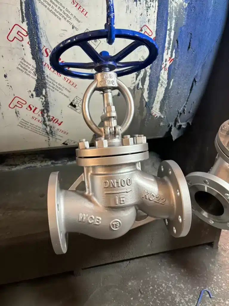
A globe valve is a linear-motion valve used to start, stop or regulate the flow of a liquid, gas or vapor. Its name originally came from the rounded shape of early valve bodies, although modern globe valves may have several different external shapes.
Inside the valve, a movable disc closes against a fixed seat. The disc is connected to a stem, which may be operated by a handwheel, gearbox, pneumatic actuator, electric actuator or hydraulic actuator. As the stem moves in a straight line, the distance between the disc and seat changes.
When the disc is lifted, fluid passes through the seat opening and changes direction as it travels through the valve body. When the disc is lowered, the available flow area becomes smaller. When the disc contacts the seat, the valve stops the flow.
This controllable relationship between disc position and flow area is the main reason a globe valve is widely used for throttling and flow control.
How Does a Globe Valve Work Step by Step?
The operation of a globe valve can be divided into five basic stages.
- The operator turns the handwheel or activates the actuator. Rotational movement from the handwheel is converted into linear movement through the threaded stem and yoke mechanism.
- The stem moves upward or downward. In many designs, turning the handwheel counterclockwise raises the stem and opens the valve, while clockwise rotation lowers the stem and closes it.
- The disc changes its position relative to the seat. Raising the disc increases the flow area, while lowering the disc reduces the flow area.
- The process fluid passes through the internal flow path. The fluid changes direction as it enters the valve body, passes through the seat opening and exits through the opposite connection.
- The disc contacts the seat to stop the flow. During full closure, the handwheel or actuator applies force through the stem so that the disc presses against the seat and forms a seal.
How a Globe Valve Opens
When the handwheel is turned to open the valve, the threaded stem moves upward. The disc connected to the stem lifts away from the valve seat. This creates an annular opening between the disc and seat through which the fluid can flow.
At the beginning of the opening movement, a small change in stem position creates a relatively small flow passage. As the disc continues to rise, the available flow area increases. The exact relationship between stem travel and flow rate depends on the disc profile, seat geometry and pressure conditions.
How a Globe Valve Closes
To close the valve, the handwheel or actuator moves the stem downward. The disc approaches the seat, reducing the available flow area. As the opening becomes smaller, fluid velocity through the restricted area may increase while downstream pressure decreases.
When the disc reaches the seat, additional stem force presses the sealing surfaces together. A correctly selected and maintained globe valve can then provide reliable shutoff.
How a Globe Valve Regulates Flow
During throttling service, the disc remains partially open. Moving the disc changes the restriction inside the valve, which changes the pressure drop and flow rate through the system.
Compared with a gate valve, the disc and seat arrangement of a globe valve provides more stable control at intermediate positions. This makes globe valves suitable for applications in which the operator must frequently adjust steam, cooling water, fuel, condensate or process flow.
Important: A standard manual globe valve can regulate flow, but demanding automatic control applications should use a properly sized globe control valve with an appropriate trim characteristic, actuator and positioner.
Main Globe Valve Parts and Their Functions
Understanding the internal components helps explain how a globe valve works and why certain failures occur.
| Globe Valve Part | Function | Selection Consideration |
|---|---|---|
| Valve body | Contains the pressure and directs the fluid through the internal flow path. | Must be compatible with pressure, temperature, fluid and piping material requirements. |
| Bonnet | Closes the top of the valve body and supports the stem and packing system. | May use bolted, welded, pressure-seal or union construction. |
| Disc or plug | Moves toward or away from the seat to control or stop flow. | Disc shape affects shutoff, throttling accuracy and resistance to erosion. |
| Seat or seat ring | Provides the stationary sealing surface against which the disc closes. | Material must resist corrosion, temperature, wear and fluid velocity. |
| Stem | Transfers motion and force from the handwheel or actuator to the disc. | Must resist mechanical loading, corrosion and galling. |
| Packing | Creates a seal around the moving stem to prevent external leakage. | Selection depends on temperature, fluid, emissions requirements and stem movement. |
| Gland and gland follower | Apply compression to the stem packing. | Incorrect adjustment can cause leakage or excessive operating friction. |
| Yoke | Supports the operating mechanism and maintains stem alignment. | Must provide sufficient strength for the required closing force. |
| Handwheel or actuator | Provides the force needed to position the disc. | Must be sized for maximum differential pressure and required operating speed. |
Why Does a Globe Valve Have a High Pressure Drop?
A globe valve normally creates a greater pressure drop than a gate valve or full-port ball valve because the fluid does not travel through a straight, unrestricted passage.
In a conventional T-pattern globe valve, the fluid enters the body, changes direction, passes through the restricted seat opening and changes direction again before leaving the valve. These changes in direction and flow area create turbulence and energy loss.
Globe valve pressure drop increases when:
- The valve is partially closed.
- The seat opening is small relative to the pipe size.
- Fluid velocity is high.
- The internal flow path contains sharp directional changes.
- The valve is undersized for the required flow rate.
- The disc, seat or valve body contains deposits or damage.
This pressure loss is not always undesirable. In a control application, the globe valve intentionally creates a variable pressure drop to regulate flow. However, in a system where low energy loss is the main priority, a globe valve may not be the most efficient isolation valve.
Globe Valve Flow Direction
Correct globe valve flow direction is important because it can affect operating torque, shutoff behavior, stem packing load, noise, erosion and valve stability.
Many conventional globe valves are installed with flow entering below the disc and leaving above the seat. This arrangement is often called flow to open because process pressure tends to help lift the disc away from the seat.
Other globe valve designs may require flow from above the disc toward the seat. This is sometimes called flow to close because process pressure helps push the disc toward the closed position.
Flow Under the Disc
With flow entering below the disc, process pressure acts upward on the disc. This arrangement can reduce the force needed to begin opening in some services. It may also reduce the tendency of certain contaminants to collect above the disc.
However, the pressure may work against the closing force, especially at high differential pressure. The operator or actuator must provide enough force to push the disc onto the seat.
Flow Over the Disc
With flow entering above the disc, process pressure can assist the closing action. This can be useful in selected high-pressure or control applications. However, pressure acting on the top of the disc may increase the force required to open the valve.
Important: Always follow the flow arrow marked on the valve body and the manufacturer’s installation instructions. The correct direction depends on the valve design, disc arrangement, actuator sizing and intended service.
Common Types of Globe Valves
T-Pattern Globe Valve
The T-pattern globe valve is the most traditional design. The inlet and outlet connections are arranged in a straight line, while the seat is positioned between them. The fluid changes direction as it passes through the valve body.
This design provides effective throttling and shutoff but generally has the highest pressure drop among common globe valve body patterns.
Y-Pattern Globe Valve
A Y-pattern globe valve positions the stem and seat at an angle to the main pipeline. This creates a smoother internal flow path than a conventional T-pattern body.
The design can reduce pressure loss and may be preferred in high-pressure, high-temperature or continuous-flow applications where the valve remains open for long periods.
Angle Globe Valve
An angle globe valve changes the direction of the pipeline, usually by 90 degrees, while also controlling the flow. It combines the function of a valve and an elbow, which can reduce the number of separate piping components.
Angle globe valves are commonly considered for boiler systems, drains, condensate lines and installations where the piping direction must change near the valve.
Needle Globe Valve
A needle-type globe valve uses a long, tapered disc or needle that fits into a small seat opening. The gradual change in flow area allows more precise adjustment of low flow rates.
Needle valves are generally used in small-bore instrumentation, sampling and pressure-control lines rather than large process pipelines.
Bellows-Sealed Globe Valve
A bellows-sealed globe valve includes a flexible metal bellows around the stem. The bellows creates an additional pressure boundary that reduces the possibility of process fluid escaping through the stem packing area.
This design is often considered for hazardous, toxic, high-purity or high-temperature media where external leakage must be minimized.
Pressure-Seal Globe Valve
A pressure-seal globe valve uses internal system pressure to improve the seal between the body and bonnet. Pressure-seal construction is commonly used in high-pressure, high-temperature power plant and steam applications.
Globe Valve Disc Types
The globe valve disc profile influences throttling performance, leakage, erosion resistance and sensitivity to contamination.
| Disc Type | Main Characteristic | Typical Use |
|---|---|---|
| Plug disc | Provides a defined contact area and can offer reliable shutoff. | General industrial isolation and moderate throttling. |
| Conventional disc | Uses a relatively simple disc profile for opening and closing. | General utility applications. |
| Needle disc | Provides gradual flow-area changes for fine adjustment. | Low-flow and instrumentation service. |
| Contoured plug | Produces a more predictable relationship between valve travel and flow. | Automatic globe control valves. |
| Soft-seated disc | Uses a polymer or resilient sealing element for tight shutoff. | Compatible low- or moderate-temperature fluids. |
| Metal-seated disc | Provides improved resistance to temperature and severe operating conditions. | Steam, high-temperature and erosive services. |
Globe Valve Advantages and Disadvantages
Advantages of a Globe Valve
- Good throttling and flow-regulation capability
- Predictable control at intermediate stem positions
- Reliable shutoff when the disc and seat are in good condition
- Suitable for frequent operation
- Available with different body, trim and actuator configurations
- The seat and disc can often be repaired or replaced
- Compatible with automatic process-control systems
- Available for high-pressure and high-temperature applications
Disadvantages of a Globe Valve
- Higher pressure drop than gate valves and full-port ball valves
- Greater energy loss in continuously open service
- Higher operating force at large sizes or high differential pressure
- More complex internal flow path
- Potential for noise, cavitation, flashing or erosion during severe throttling
- Generally unsuitable for pipeline pigging
- May be heavier and more expensive than simple isolation valves
Globe Valve vs Gate Valve
The difference between a globe valve and gate valve is one of the most common questions in industrial valve selection.
| Comparison | Globe Valve | Gate Valve |
|---|---|---|
| Primary purpose | Flow regulation and isolation | Fully open or fully closed isolation |
| Closure movement | Disc moves toward a horizontal or angled seat | Gate moves into or out of the flow path |
| Throttling performance | Good | Generally poor |
| Pressure drop when open | Relatively high | Relatively low |
| Operating travel | Moderate | Usually longer |
| Partial opening | Suitable for controlled throttling | Can damage the gate and seats |
| Typical applications | Steam control, cooling water, fuel regulation and process control | Main pipeline isolation and low-resistance flow service |
Choose a globe valve when flow adjustment is required. Choose a gate valve when the main requirement is low-pressure-loss isolation and the valve will normally remain fully open or fully closed.
Globe Valve vs Ball Valve
A ball valve uses a rotating ball with a central bore, while a globe valve uses a linearly moving disc and seat.
A full-port ball valve generally produces less pressure loss and can open or close with a quarter turn. A globe valve requires multiple turns or linear actuator travel, but it usually provides more stable throttling performance.
Ball valves are often selected for fast isolation. Globe valves are often selected for flow control, steam regulation and applications requiring frequent adjustment.
How Does a Globe Control Valve Work?
A globe control valve uses the same basic disc-and-seat principle as a manual globe valve, but an actuator automatically positions the plug in response to a control signal.
A typical globe control valve loop works as follows:
- A sensor measures pressure, temperature, level or flow.
- A controller compares the measured value with the required setpoint.
- The controller sends a signal to the valve positioner.
- The positioner adjusts the pneumatic or electric actuator.
- The actuator moves the valve stem and plug.
- The changed flow rate moves the process closer to the setpoint.
The control valve trim may be designed to provide linear, equal-percentage or quick-opening flow characteristics. Correct valve sizing is essential because an oversized control valve may operate too close to the seat, while an undersized valve may not deliver the required maximum flow.
Why Are Globe Valves Used for Steam?
A globe valve for steam is widely used because its disc and seat arrangement can provide controlled opening, reliable shutoff and resistance to frequent operation.
Steam systems often require gradual flow adjustment during startup, warm-up, pressure reduction or equipment isolation. A globe valve allows the operator to increase flow progressively rather than releasing the full steam flow immediately.
When selecting a steam globe valve, consider:
- Steam pressure and temperature
- Superheated or saturated steam conditions
- Body and trim material ratings
- Metal seat hardness and erosion resistance
- Pressure-seal or bolted-bonnet construction
- Stem packing suitability
- Condensate and water-hammer risk
- Required opening and closing force
Steam system safety: A globe valve should not be opened rapidly into a cold steam line. Proper warm-up, condensate drainage and operating procedures are necessary to reduce thermal shock and water-hammer risk.
How to Select a Globe Valve
Selecting the correct globe valve requires more than matching the nominal pipe size. The valve must be evaluated as part of the complete piping and process system.
1. Identify the Process Fluid
Determine whether the valve will handle water, steam, oil, gas, chemicals, condensate or another medium. Confirm concentration, solids content, corrosiveness, toxicity and contamination limits.
2. Confirm Pressure and Temperature
Record normal, minimum, maximum and design conditions. The body, bonnet, seat, packing and gasket materials must remain suitable throughout the entire operating range.
3. Define the Valve Function
Determine whether the globe valve is intended for isolation, manual throttling, automatic control, pressure reduction, bypass service or emergency shutdown. The required function affects the body pattern, disc profile and actuator selection.
4. Calculate the Required Flow Capacity
For control applications, use actual flow, pressure and fluid-property data to calculate the required valve flow coefficient. Do not select a globe control valve only by matching it to the pipe diameter.
5. Select the Body Pattern
- Use a T-pattern globe valve for general throttling and shutoff.
- Consider a Y-pattern globe valve when reduced pressure loss is important.
- Use an angle globe valve when the piping must change direction.
- Consider bellows-sealed construction for low-emission service.
- Consider pressure-seal construction for high-pressure steam systems.
6. Select the Body and Trim Materials
Common globe valve body materials include cast iron, ductile iron, carbon steel, stainless steel, alloy steel and special corrosion-resistant alloys. Trim materials must resist wear, corrosion, galling and erosion at the seat and stem.
7. Determine the End Connection
Globe valves are available with threaded, socket-weld, butt-weld and flanged ends. The connection must match the pipe class, pressure rating, maintenance requirements and applicable project standards.
8. Select Manual or Automatic Operation
Manual globe valves may use a handwheel or gearbox. Automated globe valves may use pneumatic, electric or hydraulic actuators. The actuator must produce enough thrust to move and seat the disc under the maximum expected differential pressure.
Globe Valve Selection Checklist
- Process fluid and concentration
- Normal and maximum flow rate
- Inlet and outlet pressure
- Minimum and maximum temperature
- Pipe size and connection standard
- Required pressure class
- Body and trim materials
- Shutoff leakage requirement
- Manual or automatic operation
- Fail-open, fail-closed or fail-in-place position
- Noise, cavitation and erosion risk
- Required inspection and certification documents
Globe Valve Installation Guide
Correct installation protects the seat, stem, packing, valve body and connected piping. Poor alignment or incorrect flow direction can shorten valve life even when the valve itself is correctly selected.
Before Installation
- Confirm the valve size, pressure class, material and identification tag.
- Check the body flow arrow and required installation direction.
- Inspect the valve for shipping damage or contamination.
- Flush weld slag, rust, sand and debris from the pipeline.
- Confirm that the mating connections are correctly aligned.
- Provide adequate pipe support.
- Verify that there is sufficient space for handwheel or actuator movement.
During Installation
- Position the valve according to the marked flow direction.
- Prevent excessive pipe loads from acting on the valve body.
- Use compatible gaskets, bolts and joint materials.
- Tighten flange bolts gradually in a cross pattern.
- Protect the valve from welding heat and debris when applicable.
- Do not use the handwheel or actuator as a lifting point.
After Installation
- Operate the valve through its full travel.
- Confirm smooth stem movement.
- Check the body, bonnet, flanges and packing for leakage.
- Verify actuator travel and limit settings.
- Perform the required pressure and functional tests.
- Record the installation and test results.
Globe Valve Maintenance
A globe valve should be inspected according to service severity, operating frequency and the consequences of failure. Valves in high-temperature, corrosive or frequently cycled service normally require more attention than valves in clean, stable utility systems.
Routine Inspection Points
- Stem packing leakage
- Bonnet and body-joint leakage
- Flange or threaded connection leakage
- Changes in handwheel torque
- Incomplete opening or closing
- Internal seat leakage
- Stem corrosion or damage
- Actuator air, hydraulic or electrical condition
- Abnormal vibration, noise or temperature
Stem Packing Adjustment
If leakage appears around the stem, the packing gland may require adjustment. Packing compression should be increased gradually and evenly. Excessive tightening can increase stem friction, damage the packing and prevent smooth valve operation.
If adjustment does not stop the leakage, the packing may need replacement. The line must be safely isolated, depressurized, drained and cooled before packing maintenance.
Disc and Seat Inspection
Internal leakage may result from erosion, corrosion, foreign material, misalignment or damaged sealing surfaces. After safe disassembly, inspect the disc and seat for scratches, wire drawing, pitting, deformation or deposits.
Depending on the valve design and damage level, the sealing surfaces may be cleaned, lapped, machined or replaced.
Common Globe Valve Problems and Solutions
| Problem | Possible Cause | Recommended Action |
|---|---|---|
| Valve is difficult to operate | Packing is too tight, the stem is damaged, deposits are present or differential pressure is too high. | Inspect packing adjustment, stem condition, internal deposits and actuator sizing. |
| Leakage through the closed valve | Damaged seat, eroded disc, trapped debris or insufficient closing force. | Confirm full closure, safely flush if permitted and inspect the disc and seat. |
| Leakage around the stem | Worn packing, thermal cycling, loose gland or damaged stem surface. | Adjust or replace the packing and inspect the stem. |
| Leakage at the bonnet | Damaged gasket, loose bolting, thermal movement or sealing-surface damage. | Isolate the valve and inspect the gasket, bolts and joint surfaces. |
| Noise or vibration during throttling | High velocity, cavitation, flashing, excessive pressure drop or an oversized valve. | Review valve sizing, trim design, pressure conditions and operating position. |
| Rapid seat erosion | Severe throttling, abrasive particles, incorrect trim material or excessive velocity. | Use suitable hardened trim, improve valve sizing or select a severe-service control valve. |
| Actuator cannot close the valve | Insufficient thrust, high differential pressure, incorrect flow direction or mechanical obstruction. | Verify actuator sizing, process conditions, installation direction and internal valve condition. |
When Should You Use a Globe Valve?
A globe valve is a strong choice when the application requires controlled flow adjustment, frequent operation or reliable shutoff with a linear-motion design.
Typical globe valve applications include:
- Steam supply and distribution
- Boiler feedwater systems
- Cooling water regulation
- Condensate and drain lines
- Fuel oil systems
- Compressed air systems
- Chemical process lines
- Bypass and recirculation lines
- Pressure-reducing stations
- Automatic flow-control loops
- Power generation facilities
- Oil and gas processing plants
When Is a Globe Valve Not the Best Choice?
A globe valve may not be the best option when the system requires minimum pressure loss, unrestricted flow, pipeline pigging or very fast quarter-turn isolation.
Alternative valve types may be more appropriate when:
- A full-bore flow path is required.
- The valve will remain fully open for most of its service life.
- The system is highly sensitive to pressure loss.
- The medium contains large solids or fibrous material.
- Very rapid opening or closing is required.
- Compact dimensions and low weight are primary requirements.
In these conditions, a gate valve, ball valve, butterfly valve or another specialized valve may provide better overall performance.
Frequently Asked Questions About Globe Valves
How does a globe valve work?
A globe valve works by moving a disc or plug toward or away from a fixed seat. Raising the disc opens the flow passage, lowering it restricts the flow and pressing it against the seat stops the flow.
What is the main purpose of a globe valve?
The main purpose of a globe valve is to regulate, start or stop fluid flow. It is particularly useful when stable throttling and frequent flow adjustment are required.
Can a globe valve be used for isolation?
Yes. A correctly selected globe valve can provide reliable isolation. However, it normally creates more pressure drop in the open position than a gate valve or full-port ball valve.
Which way should a globe valve be installed?
Install the globe valve according to the flow arrow on the body and the manufacturer’s instructions. Some designs use flow under the disc, while others require flow over the disc.
Why is a globe valve suitable for throttling?
The linear movement of the disc creates a controlled change in the flow area. This provides more stable regulation at partially open positions than valves designed mainly for isolation.
Why does a globe valve have a high pressure drop?
The fluid changes direction and passes through a restricted seat opening inside the valve. These directional and area changes create turbulence and energy loss.
Can a globe valve be installed vertically?
Many globe valves can be installed in vertical piping, but actuator orientation, flow direction, drainage, maintenance access and manufacturer limitations must be checked.
What is the difference between a globe valve and a globe control valve?
A manual globe valve is positioned by a handwheel or manual gearbox. A globe control valve normally uses an actuator, positioner and specially designed trim to regulate flow automatically in response to a control signal.
Is a globe valve normally open or normally closed?
A manual globe valve does not have a fixed normal position. An actuated globe valve can be configured to fail open, fail closed or remain in its last position, depending on the actuator and process-safety requirement.
How often should a globe valve be maintained?
Maintenance frequency depends on fluid condition, temperature, operating cycles, pressure drop and service criticality. Critical valves should be included in a documented inspection and functional-testing program.
Conclusion
A globe valve works by using linear stem movement to position a disc relative to a fixed seat. This operating principle allows the valve to start, stop and regulate fluid flow with greater control than many valves designed only for isolation.
The best globe valve performance depends on correct sizing, body pattern, flow direction, disc design, material selection and actuator capacity. Engineers should review the complete process conditions rather than selecting a valve only by pipe size or pressure class.
When properly selected and maintained, a globe valve can provide dependable throttling, frequent operation and effective shutoff in steam, water, oil, gas and industrial process systems.