


Technical Guide
How Does a Motorized Ball Valve Work?
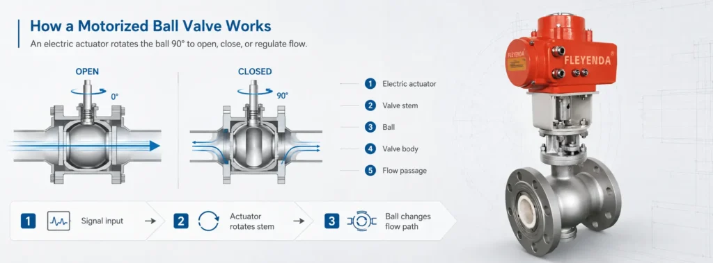
A motorized ball valve works by using an electric actuator to rotate a ball inside the valve body. When the hole through the ball is aligned with the pipeline, fluid can pass through. When the actuator turns the ball 90 degrees, the hole is no longer aligned with the pipeline, and the valve blocks the flow.
In practical terms, a motorized ball valve converts an electrical control signal into mechanical rotary motion. This allows a pipeline to be opened, closed, or regulated automatically without manual operation. It is commonly used in HVAC systems, water treatment equipment, irrigation systems, industrial automation, smart buildings, and fluid control applications where remote or automatic valve operation is required.
Working Principle of a Motorized Ball Valve
The basic working principle of a motorized ball valve is quarter-turn rotation. Inside the valve body, there is a spherical ball with a bore through its center. This bore is the flow passage. When the bore is parallel to the pipeline, the valve is open and the media can pass through. When the ball rotates 90 degrees, the bore becomes perpendicular to the pipeline and the solid side of the ball blocks the flow path.
The movement is simple, but it is highly effective. A manual ball valve uses a handle to rotate the ball, while a motorized ball valve uses an electric actuator to complete the same motion automatically. The actuator receives a signal from a control device, drives an internal motor, transfers torque through a gearbox, and rotates the valve stem. The stem then turns the ball to the open, closed, or required intermediate position.
This quarter-turn design gives the motorized ball valve several practical advantages. It has a compact structure, fast response, low pressure drop, and reliable sealing performance. For full-port designs, the bore diameter is close to the pipe diameter, so the pressure loss is relatively low compared with many other valve types.
- The controller sends an open, close, or regulating signal to the actuator.
- The actuator motor starts running after receiving the signal.
- The gearbox reduces motor speed and increases torque.
- The valve stem transfers torque from the actuator to the ball.
- The ball rotates to open, close, or regulate the flow path.
Main Structure of a Motorized Ball Valve
A motorized ball valve is made of two main parts: the ball valve and the electric actuator. The ball valve is responsible for sealing and flow control, while the actuator provides automatic operation. Although designs vary by size, pressure rating, material, and control method, most motorized ball valves share a similar basic structure.
The valve body is the pressure-bearing housing of the valve. It contains the flow channel and supports the internal sealing parts. Common body materials include brass, stainless steel, carbon steel, PVC, and UPVC. Brass motorized ball valves are often used for water supply, plumbing, and HVAC systems. Stainless steel motorized ball valves are more suitable for industrial fluids, corrosive media, food-grade systems, and chemical applications.
The ball is the main shut-off component. It rotates inside the valve body and controls whether the media can pass through. Around the ball, valve seats provide sealing support. These seats are usually made from PTFE or other engineering materials. The stem connects the ball to the actuator, allowing torque from the actuator to rotate the ball. A reliable stem seal is important because it helps prevent leakage and improves long-term service life.
The electric actuator is mounted on top of the valve. It usually contains a motor, gearbox, limit switches, wiring terminals, position indicator, and protective housing. Some actuators also include manual override, position feedback, fail-safe return, or modulating control. The quality of the actuator has a direct impact on the reliability, response time, control accuracy, and service life of the motorized ball valve.
How the Actuator and Control System Work
The actuator is the part that makes the ball valve automatic. When the actuator receives a signal from a PLC, thermostat, timer, relay, sensor, or building automation system, the motor starts to run. Since the motor speed is usually too high and the torque is too low for direct valve operation, the actuator uses a gearbox to reduce speed and increase output torque. This allows the valve to open and close smoothly under actual pipeline pressure.
Limit switches are used to stop the motor when the valve reaches the fully open or fully closed position. This prevents over-rotation and protects the motor and gears from damage. In many motorized ball valves, power is consumed only during opening or closing. Once the valve reaches its final position, the limit switch cuts power to the motor.
Motorized ball valves can be designed for different control methods. An on/off motorized ball valve moves only between fully open and fully closed positions. It is suitable for automatic shut-off, pipeline isolation, irrigation zones, tank filling, and HVAC zone control. A modulating motorized ball valve can stop at different opening angles based on a signal such as 0-10V, 4-20mA, or PWM. This type is used when proportional flow control is required.
Wiring method also depends on actuator design. A 2-wire motorized ball valve is often used for simple open and close control. A 3-wire motorized ball valve usually has one common wire, one open control wire, and one close control wire. Common actuator voltages include 12V DC, 24V AC/DC, 110V AC, and 220V AC. For HVAC and control panel applications, 24V motorized ball valves are widely used because they are safer and easier to integrate with control systems.
Common Types of Motorized Ball Valves
Motorized ball valves can be classified by flow path, control function, port design, and fail-safe position. A 2-way motorized ball valve has one inlet and one outlet. It is mainly used to open or close a pipeline and is the most common type in water systems, HVAC pipelines, irrigation, and general automation systems.
A 3-way motorized ball valve has three ports and can be used for mixing, diverting, or switching flow direction. This type is often used in heating and cooling systems, water treatment equipment, and process control applications where flow must be redirected between different pipelines.
Motorized ball valves can also be normally closed, normally open, or stay-in-place after power loss, depending on actuator design. A normally closed motorized ball valve is often used where shutting off flow is the safer condition. A normally open motorized ball valve is used where continuous flow is normally required. For safety-critical systems, a fail-safe actuator may be used to move the valve to a safe position during power failure.
In terms of flow capacity, full-port motorized ball valves provide a larger internal bore and lower pressure drop. Reduced-port designs are more compact and economical, but they create more flow resistance. For systems where maintaining flow capacity is important, a full-port motorized ball valve is usually the better choice.
How to Select the Right Motorized Ball Valve
Selecting a motorized ball valve should not be based only on pipe size. The correct valve depends on the media, working pressure, temperature, voltage, control method, body material, sealing material, actuator torque, and installation environment. If one of these factors is ignored, the valve may leak, fail to operate, or have a shorter service life.
The first factor is media compatibility. Water, air, oil, gas, steam, seawater, and chemical fluids may require different valve body and seal materials. Brass is suitable for many general water applications, while stainless steel is better for corrosive media, industrial fluids, and more demanding environments. Plastic materials such as PVC or UPVC may be used in some water treatment and chemical systems.
Pressure and temperature ratings must also match the system conditions. The selected valve should safely handle the normal operating pressure as well as possible pressure fluctuations. Temperature affects the valve seats, seals, and actuator. High-temperature water, steam, oil, or process fluids may require special sealing materials and heat protection for the actuator.
Actuator selection is equally important. The voltage must match the available power supply and control system. The actuator must also provide enough torque to rotate the ball under real working conditions. Larger valve sizes, higher pressure, viscous fluids, dirty media, or long periods of inactivity can increase the required torque. For outdoor, humid, dusty, or washdown environments, the actuator housing should have suitable protection, and cable entries should be properly sealed.
| Selection Factor | What to Check | Why It Matters |
|---|---|---|
| Media | Water, air, oil, gas, steam, chemical fluid, seawater | Determines body and seal material compatibility |
| Valve Size | Pipe size and required flow rate | Affects flow capacity and pressure drop |
| Pressure Rating | Normal pressure and pressure fluctuation | Prevents leakage, deformation, or valve failure |
| Temperature | Media temperature and ambient temperature | Affects seats, seals, and actuator reliability |
| Voltage | 12V DC, 24V AC/DC, 110V AC, 220V AC | Must match the power supply and control system |
| Control Type | On/off, modulating, fail-safe | Determines how the valve operates in the system |
| Actuator Torque | Valve size, pressure, media viscosity, operating frequency | Ensures the valve can open and close reliably |
Common Applications of Motorized Ball Valves
Motorized ball valves are used when automatic operation improves efficiency, safety, or system control. In HVAC systems, they are used for chilled water, hot water, fan coil units, floor heating, boiler systems, and zone control. They allow heating and cooling circuits to be controlled automatically according to temperature, time, or building management system commands.
In water treatment systems, motorized ball valves are used in filtration, reverse osmosis, softening, dosing, wastewater treatment, and automatic flushing processes. These systems often require repeated valve operation, remote control, or timed switching, making motorized valves more practical than manual valves.
Irrigation and agricultural systems use motorized ball valves to control water distribution through timers, soil moisture sensors, or central controllers. In industrial automation, they are used to control water, air, oil, gas, and compatible chemical fluids in process equipment and production lines. In smart buildings, they can be used for water leak protection, remote shut-off, heating control, cooling control, and building automation.
Motorized Ball Valve vs Manual Ball Valve
A motorized ball valve and a manual ball valve use the same basic ball rotation principle, but they are operated in different ways. A manual ball valve requires an operator to turn the handle by hand. A motorized ball valve uses an electric actuator to rotate the ball automatically.
For simple local shut-off, a manual ball valve is usually enough. For remote control, automatic operation, frequent switching, timed control, sensor-based control, or integration with a PLC or building automation system, a motorized ball valve is the better choice.
| Item | Motorized Ball Valve | Manual Ball Valve |
|---|---|---|
| Operating Method | Operated automatically by an electric actuator | Operated manually by turning a handle |
| Control Distance | Can be controlled remotely | Requires local manual operation |
| Automation | Can connect to PLCs, relays, sensors, timers, thermostats, or BMS | Cannot be automated unless an actuator is added |
| Power Requirement | Requires electrical power for actuator operation | No power required |
| Operation Frequency | Suitable for frequent or scheduled operation | Better for occasional manual operation |
| System Feedback | Can provide open/close feedback depending on actuator type | No electrical position feedback |
| Typical Use | HVAC, water treatment, irrigation, industrial automation, smart buildings | Maintenance shut-off, local isolation, simple pipeline control |
In short, a manual ball valve is suitable when the valve only needs to be operated occasionally by hand. A motorized ball valve is suitable when the system needs automatic control, remote operation, timed switching, sensor-based operation, or connection to a wider control system.
Common Problems and Troubleshooting
If a motorized ball valve does not operate correctly, the problem may come from the actuator, wiring, power supply, control signal, valve body, or internal blockage. A systematic check is usually more effective than replacing the valve immediately.
If the valve does not open or close, first confirm that the power supply voltage matches the actuator rating. Then check the wiring terminals, control signal, fuse, and limit switches. If the actuator is powered but does not rotate, the motor or gearbox may be damaged, or the actuator torque may be insufficient for the valve.
If the valve stops halfway, possible causes include insufficient actuator torque, internal debris, damaged gears, excessive pipeline pressure, or a ball that is difficult to rotate after long inactivity. If the valve leaks when closed, the issue may be damaged seats, particles trapped between the ball and seat, incorrect material selection, or long-term wear.
If the actuator overheats, the valve may be wired incorrectly, continuously powered beyond its duty cycle, or forced to operate under excessive torque. If the control system cannot detect valve position, check the feedback wiring, auxiliary limit switches, and controller input settings.
FAQ
How does a motorized ball valve work?
A motorized ball valve uses an electric actuator to rotate a ball inside the valve body. When the bore of the ball aligns with the pipeline, the valve opens. When the ball rotates 90 degrees, the flow path is blocked and the valve closes.
What is a motorized ball valve used for?
It is used for automatic flow control in HVAC systems, water treatment, irrigation, industrial automation, smart buildings, plumbing systems, and process equipment.
Can a motorized ball valve regulate flow?
Yes. A standard on/off motorized ball valve is mainly used for opening and closing, while a modulating motorized ball valve can regulate flow by stopping at different opening angles.
What voltage is common for motorized ball valves?
Common voltages include 12V DC, 24V AC/DC, 110V AC, and 220V AC. The correct voltage depends on the power supply and control system.
What is the difference between a motorized ball valve and a manual ball valve?
A manual ball valve is operated by hand, while a motorized ball valve is operated automatically by an electric actuator. Motorized ball valves are better for remote control, automation, frequent operation, and system integration.
Does a motorized ball valve stay open after power is removed?
It depends on the actuator design. Some valves stay in the last position, some return open, and some return closed. For safety-related applications, a fail-safe actuator should be selected.
Conclusion
A motorized ball valve works by using an electric actuator to rotate a ball inside the valve body. This quarter-turn movement allows the valve to open, close, or regulate flow automatically. Its simple structure, reliable sealing, low pressure drop, and easy integration with control systems make it a practical choice for many fluid control applications.
When selecting a motorized ball valve, buyers should consider the media, valve size, pressure, temperature, voltage, control type, body material, seal material, actuator torque, and installation environment. A correctly selected motorized ball valve can improve automation efficiency, reduce manual operation, and provide stable long-term pipeline control.