


Electric 3-Way Flanged Ball Valve
The FLE-Q-TF electric 3-way flanged ball valve is built for automated flow diversion, distribution, bypass and selected mixing duties. L-port and T-port ball configurations allow one actuator to route flow between three pipeline connections, while flanged ends provide secure integration into industrial process systems.
- Gövde
- CF8 / CF8M / WCB
- Temperature
- −20°C to +180°C
- Function
- Divert / Mix / Bypass
- Protection
- IP67 / IP68 Option
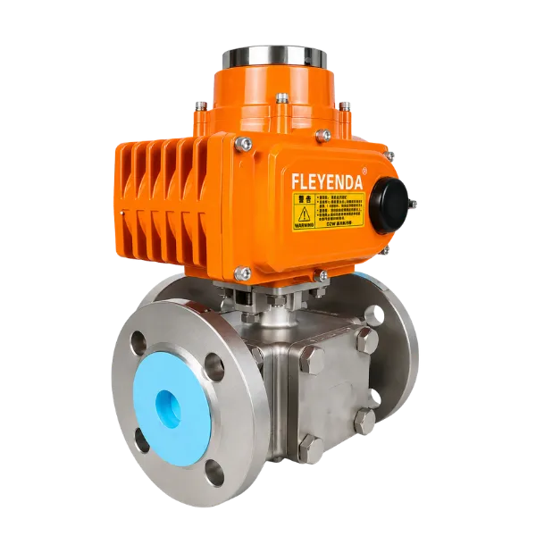
One valve for diversion, bypass and multi-line routing
A 3-way ball valve solves a different problem from a standard 2-way isolation valve. Instead of simply opening or closing one pipeline, the FLE-Q-TF selects how the connected branches communicate.
This makes the valve useful where a process must switch between two outlets, direct one source to different equipment, create a bypass route or combine selected flow paths. The required L-port or T-port configuration should be defined before actuator selection.
- 01Route one inlet to either of two downstream branches.
- 02Create bypass logic around filters, heat exchangers or process equipment.
- 03Use T-port arrangements where the process requires multiple connected paths.
- 04Flanged construction supports fixed industrial piping and larger line sizes.
Electric 3-Way Flanged Ball Valve specifications
Standard configurations cover common industrial flange standards, materials, voltages and actuator options. Final selection should follow the actual flow path and process conditions.
| Model | FLE-Q-TF |
|---|---|
| Flow configuration | L-port or T-port |
| Size range | DN15–DN200 (½″–8″) |
| Working pressure | PN10–PN40 / ANSI Class 150–300 |
| Working temperature | −20°C to +180°C, depending on seat and medium |
| Body material | Stainless Steel CF8 / CF8M or Carbon Steel WCB |
| Connection | Flanged — DIN / ANSI / JIS options |
| Applicable media | Water, air, oil, steam, acid, alkali and compatible process liquids |
| Aktüatör | Electric rotary actuator; on/off, regulating or intelligent configurations |
| Voltage options | AC110V, AC220V, AC380V, DC24V |
| Design references | GB/T 12237, ASME B16.34, API 6D, ISO 5211 |
| Testing | API 598, EN 12266-1, ISO 5208 |
| Fire-safe option | API 607 / ISO 10497 on selected configurations |
| Protection | IP67 standard on selected actuators; IP68 optional |
| Explosion-proof option | Selected Ex d II BT4 / CT4 / CT6 Gb actuator configurations |
Choose the internal flow path before choosing the actuator
The most important decision on a 3-way ball valve is not voltage or actuator size. It is the ball drilling and required port-to-port connection in each operating position.
3-way routing valve vs 2-way shutoff valve
Both use electric quarter-turn actuation, but they solve different piping problems. The 3-way valve is selected for path management; the 2-way valve is selected primarily for simple isolation.
Actuator configuration for repeatable routing
The actuator must provide sufficient torque, correct stop positions and the required control interface for the selected L-port or T-port routing sequence.
| Aktüatör | Standard time / torque | Optional time / torque | Weight |
|---|---|---|---|
| FLE-105 | 25s / 50Nm | 4s / 20Nm; 10s / 30Nm | 2,2 kg |
| FLE-110 | 25s / 100Nm | 15s / 50Nm | 5,1 kg |
| FLE-116 | 25s / 160Nm | 15s / 80Nm | 5,1 kg |
| FLE-120 | 25s / 200Nm | 15s / 100Nm | 7,5 kg |
| FLE-140 | 25s / 400Nm | 15s / 200Nm | 7,5 kg |
| FLE-160 | 25s / 600Nm | 15s / 300Nm | 8,1 kg |
| FLE-1100 | 50s / 1000Nm | 25s / 500Nm | 12,7 kg |
| FLE-1200 | 50s / 2000Nm | 25s / 1000Nm | 12,7 kg |
Where 3-way electric flanged ball valves add value
The strongest use cases are systems that need repeatable routing between branches, equipment or process stages rather than simple open-close isolation.

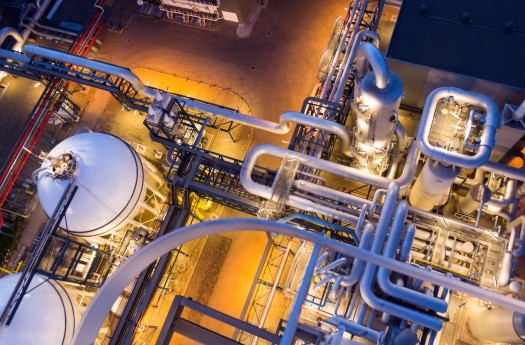
Route water between filters, treatment stages, bypass branches and distribution lines.
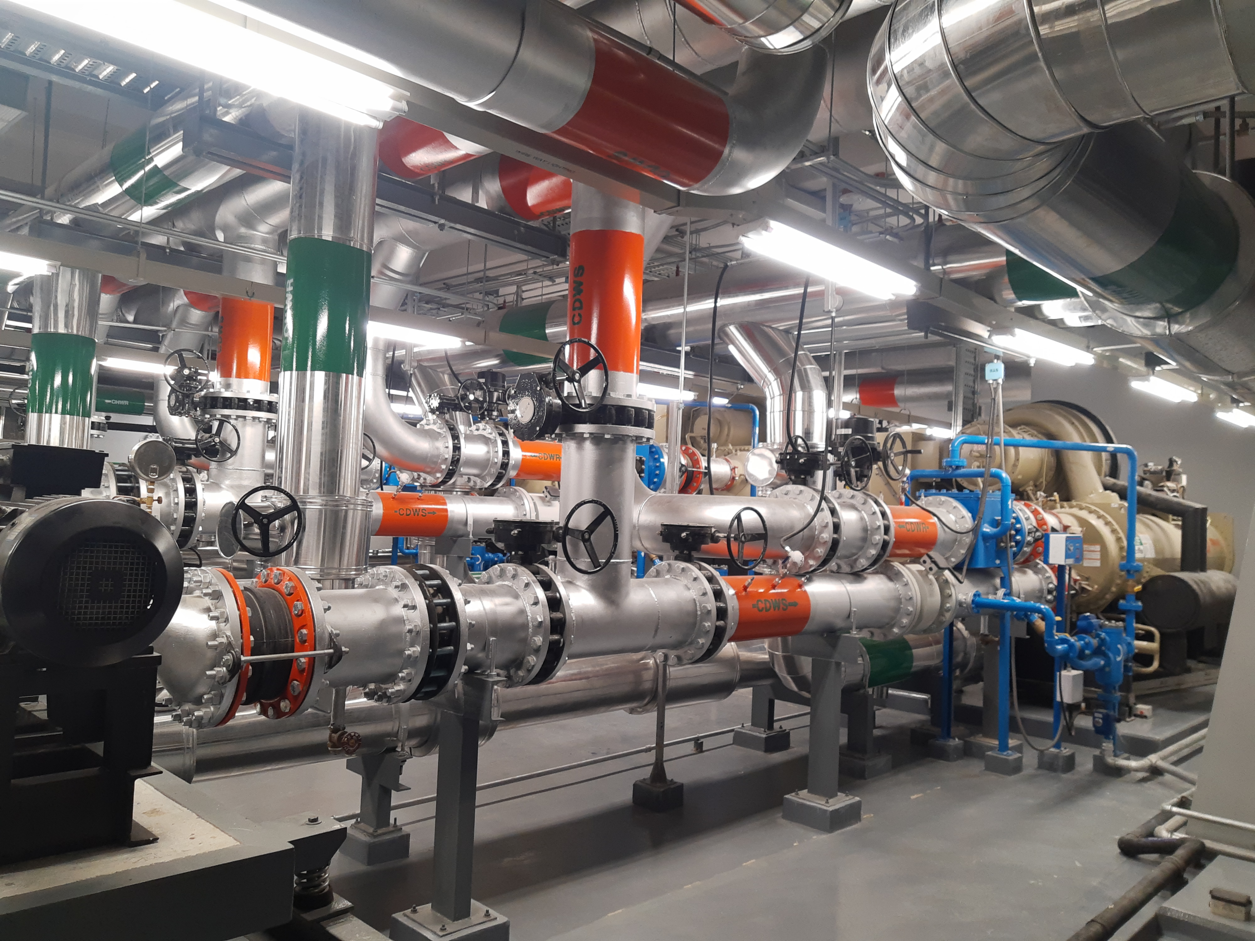
Automated routing between equipment branches, bypass loops and compatible thermal-water circuits.
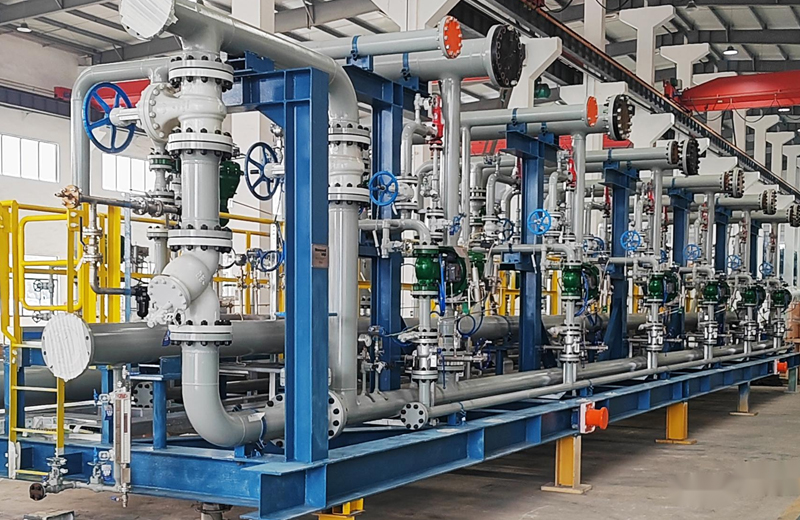
Switch flow between pumps, tanks, modules or parallel process equipment from one actuator.

Route compatible process media between tanks, lines or downstream equipment after material review.
Specify the flow scheme before the electrical options
A reliable 3-way valve selection starts with what each port must do in every operating position. Materials, size, torque and actuator controls follow from that process requirement.
Draw the three ports
Label the ports A / B / C or 1 / 2 / 3 and show the required flow direction in each position.
Choose L-port or T-port
Select the internal ball drilling from the actual diverting, distributing, bypass or mixing logic.
Confirm media & materials
Match body, ball, seat and seal materials to the fluid, concentration and temperature.
Match size & flange
Confirm DN / inch size, pressure class and ANSI, DIN, JIS or project-specific flange standard.
Define normal & fail position
Specify which ports must be connected during normal operation and after a power-loss condition.
Specify controls
Provide voltage, PLC/DCS interface, position feedback, protection level and hazardous-area requirements.
Industrial valve and actuator configurations for demanding automation
Fleyenda lists API 598 / EN 12266-1 / ISO 5208 testing references, ISO 5211 mounting and selected IP68, SIL, TÜV and explosion-proof actuator options for this product family.
Electric 3-Way Flanged Ball Valve FAQs
Questions focused on L/T-port selection, routing logic, actuator integration and process suitability.
What is the difference between an L-port and T-port 3-way ball valve?
Can the FLE-Q-TF be used for mixing as well as diverting?
What information is needed to order the correct 3-way flow path?
Can this valve integrate with PLC or DCS systems?
Which flange standards are available?
Is a 3-way ball valve the same as a V-port control valve?
Specify the three flow paths. We will match the valve and actuator.
Send the piping diagram, medium, size, pressure, temperature, flange standard, voltage and control requirement.