


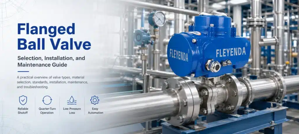
Flanged Ball Valve: Selection, Installation, and Maintenance Guide
A flanged ball valve provides fast and dependable isolation in industrial piping systems. However, its performance depends on correct sizing, compatible materials, suitable seats, proper flange alignment, and realistic operating conditions. This guide explains how to select, install, and maintain the right valve while avoiding common leakage, torque, and service-life problems.
Choosing a valve only by nominal pipe size and pressure class can result in premature seat damage, excessive operating torque, external leakage, or an incompatible flange connection. A reliable selection must consider the actual fluid, pressure, temperature, solids content, operating frequency, shutoff requirement, piping standard, and actuator conditions.
What Is a Flanged Ball Valve?
A flanged ball valve is an isolation valve with flanges integrated into both ends of its body. These flanges are bolted to matching pipeline flanges, with a gasket positioned between the sealing faces. This connection allows the valve to be removed for inspection or replacement without cutting the pipe.
Inside the valve, a drilled spherical closure element rotates around a stem. When the bore through the ball is aligned with the pipeline, fluid passes through the valve. Rotating the ball approximately 90 degrees places the solid side of the ball across the flow path and isolates the line.
Корпус клапана
The body contains the process pressure and supports the internal components. Common constructions include one-piece, two-piece, three-piece, split-body, top-entry, and fully welded designs.
Ball and Seats
The polished ball forms the shutoff interface with resilient polymer seats or engineered metal seats. Their compatibility with the process fluid is essential for reliable sealing.
Stem and Operator
The stem transfers torque from a lever, gearbox, pneumatic actuator, hydraulic actuator, or electric actuator to the ball.
How Does a Flanged Ball Valve Work?
A standard ball valve is a quarter-turn valve. In most installations, a handle positioned parallel to the pipeline indicates that the valve is open. A handle positioned perpendicular to the pipeline usually indicates that the valve is closed.
Actuated valves use mechanical travel stops and position indicators to identify the same operating positions. Limit switches or position transmitters may also be used to send valve status information to a control system.
During closure, the ball rotates against the seats and blocks the flow path. The pressure-assisted sealing behavior depends on the valve design. In a floating ball valve, line pressure pushes the ball toward the downstream seat. In a trunnion-mounted design, the ball is mechanically supported while movable seat assemblies are energized against it.
Important operating rule: A standard isolation ball valve should normally be fully open or fully closed. Holding it at an intermediate position can create high-velocity jets that erode the seats and ball. Use a valve specifically designed for throttling or control service when flow regulation is required.
Why Use a Flanged Ball Valve?
Reliable Shutoff
A properly selected ball-and-seat combination can provide tight isolation for liquids and gases. The wiping action between the ball and seats can also help remove light deposits from the sealing surface during operation.
Fast Quarter-Turn Operation
The valve moves from open to closed with approximately one-quarter turn. This makes it suitable for manual isolation, emergency shutdown systems, and automated process sequences that require a rapid response.
Low Pressure Loss
A full-port flanged ball valve has a bore close to the internal diameter of the connected pipe. When fully open, it creates a relatively straight flow path with limited restriction and turbulence.
Strong and Serviceable Connections
Flanged ends are suitable for larger pipe sizes and demanding industrial service. The bolted joint also allows maintenance teams to remove the valve without welding or cutting the pipeline.
Easy Automation
Ball valves can be paired with pneumatic, electric, or hydraulic actuators. Limit switches, solenoid valves, positioners, manual overrides, and position feedback devices can be added according to the control requirements.
Common Types of Flanged Ball Valves
| Тип клапана | Construction | Typical Advantages | Selection Considerations |
|---|---|---|---|
| Плавающий шаровой кран | The ball is supported by the seats and can move slightly under line pressure. | Compact design, fewer components, economical construction, and dependable shutoff. | Common in small and medium sizes. Operating torque can increase with pressure and seat load. |
| Trunnion-Mounted Ball Valve | The ball is supported by upper and lower trunnions, while the seats move toward the ball. | Lower operating torque in large sizes and high differential-pressure service. | Usually has a higher initial cost and more complex internal construction. |
| Full-Port Ball Valve | The ball bore is approximately equal to the connected pipe bore. | Low flow resistance and better passage for cleaning tools or suspended solids. | The body is generally larger and heavier than a reduced-port valve. |
| Reduced-Port Ball Valve | The ball opening is smaller than the connected pipe bore. | Smaller, lighter, and often more economical. | Produces a greater pressure drop and may not be suitable for piggable pipelines. |
| Soft-Seated Ball Valve | Uses polymer seat materials such as PTFE, reinforced PTFE, or engineered thermoplastics. | Excellent sealing performance with relatively low operating torque. | Temperature, chemical compatibility, abrasion, and pressure limits must be checked. |
| Metal-Seated Ball Valve | Uses engineered metal-to-metal sealing surfaces, often with hard coatings. | Suitable for elevated temperatures, abrasive media, and severe service. | Usually requires more operating torque and a clearly defined leakage requirement. |
Floating Ball Valve or Trunnion Ball Valve?
Floating designs are frequently selected for general process isolation in smaller sizes and moderate operating conditions. As valve size, pressure differential, operating frequency, or reliability requirements increase, a trunnion-mounted valve may provide better torque control and seat performance.
This is not a universal size rule. The final decision should be based on the manufacturer’s pressure-temperature rating, calculated operating torque, seat design, pipeline conditions, and project specification.
How to Select the Right Flanged Ball Valve
A valve specification should be developed from the actual process conditions rather than copied from a previous project. The following selection process helps prevent compatibility and performance problems.
- Identify the process medium. Record the fluid name, concentration, phase, viscosity, solids content, particle size, corrosiveness, toxicity, and tendency to crystallize or polymerize.
- Define minimum, normal, and maximum temperatures. Do not select seats based only on the normal operating temperature. Startup, cleaning, steam-out, upset, and ambient conditions may be more severe.
- Confirm design pressure and differential pressure. Design pressure determines pressure-containment requirements, while maximum differential pressure strongly affects valve torque and actuator sizing.
- Select the correct nominal size. Match the process flow requirement, allowable pressure loss, line velocity, pipe schedule, and need for full-bore access.
- Choose full port or reduced port. Use full port when low pressure loss, line cleaning, pigging, or solids passage is important. Consider reduced port when compactness and economy are more important than minimum flow restriction.
- Select body, ball, stem, seat, packing, and gasket materials. Every wetted and pressure-retaining component must be compatible with the medium and operating temperature.
- Match the flange system. Confirm nominal size, pressure class or PN designation, flange standard, facing type, bolt pattern, gasket type, and dimensional requirements.
- Define shutoff and safety requirements. Specify acceptable seat leakage, flow direction, fire-safe testing, anti-static construction, stem retention, cavity relief, and fugitive emissions requirements where applicable.
- Calculate actuator torque. Include break-to-open torque, break-to-close torque, running torque, maximum differential pressure, seat aging, operating frequency, safety factor, air pressure, and fail-safe position.
- Review documentation and traceability. Confirm material certificates, pressure testing, inspection documents, marking, coating, dimensional drawings, and project-specific certification.
Avoid selecting by pressure class alone. A valve marked Class 300 or PN 40 does not have one pressure limit at every temperature. Allowable pressure changes with body material, temperature, seat design, and the applicable standard. Always check the manufacturer’s published pressure-temperature rating for the complete valve assembly.
Body, Trim, and Seat Material Selection
Carbon Steel
Carbon steel bodies are widely used in oil, gas, steam, utility, and general industrial applications. They provide good mechanical strength and economical performance, but corrosion allowance, coating, and fluid compatibility must be evaluated for wet or chemically aggressive environments.
Stainless Steel
Stainless steel is often selected for corrosive chemicals, clean fluids, food-related utilities, water treatment, and outdoor environments. The exact grade must be selected according to chloride concentration, temperature, cleaning chemicals, and the risk of localized corrosion.
Duplex and Nickel Alloys
Duplex stainless steels, super duplex grades, and nickel-based alloys may be necessary for seawater, sour service, strong acids, chlorides, or other severe corrosive conditions. Material selection should be based on verified corrosion data and the complete process composition.
PTFE and Reinforced PTFE Seats
PTFE-based seats provide low friction and dependable sealing in many chemical and utility services. Reinforced grades can improve dimensional stability and resistance to pressure or wear. Actual temperature and pressure capability varies by formulation and valve design.
Engineered Polymer Seats
Materials such as PEEK and other high-performance polymers may be specified for higher loads, temperatures, or demanding chemical conditions. They are not automatically suitable for every high-temperature application, so manufacturer ratings and chemical compatibility data must be checked.
Metal Seats
Metal-seated valves are commonly considered for abrasive slurries, catalyst fines, high-temperature gases, steam, ash, powders, and services that can damage polymer seats. Ball and seat coatings, hardness difference, surface finish, thermal expansion, and leakage criteria all influence performance.
| Service Condition | Possible Starting Point | Critical Verification |
|---|---|---|
| Clean water or general utility liquid | Carbon steel, stainless steel, or ductile iron body with a soft seat. | Water chemistry, temperature, corrosion allowance, and flange standard. |
| Corrosive chemical | Stainless steel, duplex, lined construction, or special alloy. | Exact concentration, contaminants, temperature, and elastomer compatibility. |
| Abrasive slurry or powder | Metal-seated valve with protected stem and hardened trim. | Particle hardness, size, velocity, solids percentage, and cavity accumulation. |
| High-temperature service | Metal seats, extended stem, and high-temperature packing. | Thermal cycling, body rating, insulation, actuator temperature, and leakage class. |
| Volatile or hazardous fluid | Low-emission stem sealing and suitable body-joint construction. | Fugitive emission qualification, fire-safe requirements, and cavity pressure management. |
Flanged Ball Valve Standards and Specifications
Applicable standards depend on the industry, region, valve construction, and project specification. A purchase order should identify the required standard and edition rather than simply stating that the valve must be “standard.”
- API 608: Commonly specified for metal ball valves with flanged, threaded, and welding ends in petroleum and process applications.
- ASME B16.34: Covers valve pressure-temperature ratings, materials, dimensions, testing, and marking requirements.
- ASME B16.5: Defines dimensional and rating requirements for many pipe flanges and flanged fittings.
- ASME B16.10: Addresses face-to-face and end-to-end valve dimensions to support installation interchangeability.
- ISO 5211: Defines interfaces for attaching part-turn actuators to industrial valves.
- ISO 15848: Provides testing and qualification procedures related to fugitive emissions from valve stem seals and body joints.
Depending on the application, the specification may also include fire-safe testing, pipeline valve requirements, sour-service material restrictions, sanitary standards, marine approvals, emissions testing, or customer-specific inspection procedures.
Flange compatibility check: The valve flange and pipeline flange must use the same dimensional system and compatible facing. Similar nominal sizes from different standards are not necessarily interchangeable.
Flanged Ball Valve Installation Guide
Correct installation is essential to valve life. Even a high-quality valve can leak or become difficult to operate when installed between misaligned flanges, exposed to welding debris, or loaded by unsupported piping.
Before Installation
- Verify the valve tag, size, pressure rating, materials, and flow direction requirements.
- Confirm that maximum pressure and temperature are within the valve rating.
- Inspect the flange faces, ball bore, seats, stem, and body for shipping damage.
- Keep protective flange covers in place until the valve is ready to be installed.
- Remove welding slag, metal chips, scale, dirt, and other debris from the pipeline.
- Check that the valve can move through its full operating travel without obstruction.
- Confirm sufficient clearance for the handle, gearbox, actuator, and future maintenance.
Align the Pipeline Correctly
Pipeline flanges must be parallel, concentric, and separated by the correct distance. Do not use the valve body or flange bolts to pull misaligned piping into position. This can distort the body, overload the flanges, damage the gasket, increase operating torque, and create external leakage.
Select the Correct Gasket and Bolting
Use a gasket compatible with the flange facing, pressure, temperature, process medium, and project standard. Bolts, studs, nuts, lubrication, and tightening procedures should meet the piping specification. Keep the gasket centered so that it does not project into the valve bore.
Tighten Bolts Evenly
Initially hand-tighten the bolting, then tighten gradually in a cross or star pattern. Multiple controlled passes help distribute gasket compression evenly. Use the torque or tensioning procedure specified by the gasket, flange, and piping engineering requirements.
Support Heavy Operators
Large gearboxes and actuators can place additional loads on the valve neck and pipeline. Provide suitable supports when required, especially when the actuator is mounted horizontally or where vibration is present. Never lift a heavy valve by its handwheel, lever, actuator, tubing, or accessories.
Flush and Test the System
Flush new piping thoroughly before placing the valve into normal service. Keep the valve in the position required by the manufacturer’s instructions during flushing and pressure testing. Test pressure, valve position, test medium, and test duration must comply with the applicable procedure and must not exceed permitted valve limits.
Safety notice: Installation and commissioning must be completed by qualified personnel. Before working on a valve, isolate the system, depressurize it, drain trapped fluid, verify temperature, release stored actuator energy, and apply the site’s lockout and tagout procedure.
Flanged Ball Valve Maintenance
Maintenance frequency should reflect the fluid, operating cycle, pressure, temperature, emissions requirement, criticality, and site experience. Valves in clean and stable service may need limited attention, while abrasive, corrosive, thermal-cycling, or rarely operated valves require closer monitoring.
Routine Inspection
- Inspect flange joints, body joints, drain fittings, and stem areas for leakage.
- Check for corrosion, coating damage, unusual noise, vibration, and external mechanical loads.
- Verify that position indicators match the actual open and closed positions.
- Inspect pneumatic tubing, solenoid valves, wiring, switches, and actuator accessories.
- Record operating time, actuator pressure, torque trends, and recurring abnormalities.
Periodic Operation
Valves that remain in one position for long periods may develop increased breakaway torque because of deposits, corrosion, or seat set. Where process safety permits, include periodic partial-stroke or full-stroke testing in the maintenance program.
Stem Packing Adjustment
Minor stem leakage may sometimes be corrected by carefully adjusting the packing gland according to the manufacturer’s procedure. Uneven or excessive tightening can increase operating torque, damage the packing, or prevent proper valve movement.
Seat and Seal Replacement
Persistent through-seat leakage normally requires internal inspection. Depressurize, drain, decontaminate, and remove the valve in accordance with the approved procedure. Replace seats, body seals, packing, and other recommended soft parts as a matched service kit.
Actuator Maintenance
Actuator springs, seals, bearings, gear trains, air supplies, and electrical components have their own inspection requirements. After any actuator or coupling work, confirm rotation direction, travel stops, fail position, position feedback, and full valve stroke before returning the assembly to service.
Flanged Ball Valve Troubleshooting
| Задача | Possible Causes | Recommended Checks |
|---|---|---|
| Leakage through the closed valve | Damaged seats, debris on the sealing surface, eroded ball, incomplete travel, or unsuitable flow conditions. | Confirm full closure, check travel stops, flush where permitted, review differential pressure, and inspect the ball and seats. |
| Leakage around the stem | Loose packing gland, worn packing, thermal cycling, stem damage, or excessive side load. | Follow the approved packing adjustment procedure and replace damaged sealing components when necessary. |
| Leakage at the flange joint | Incorrect gasket, poor alignment, uneven bolt load, damaged facing, piping stress, or temperature cycling. | Depressurize the line, inspect alignment and flange faces, verify the gasket, and repeat the approved bolting procedure. |
| High operating torque | Pressure above design assumptions, seat swelling, deposits, corrosion, packing overtightening, body distortion, or an undersized actuator. | Check process conditions, flange alignment, packing load, actuator output, and internal contamination. |
| Valve will not reach full travel | Obstruction in the bore, incorrect stop setting, actuator fault, coupling damage, inadequate air pressure, or incorrect voltage. | Isolate the system and inspect the actuator, coupling, stops, utilities, and internal flow passage. |
| Valve closes too quickly | Actuator speed is not controlled, actuator is oversized, or control accessories are incorrectly selected. | Review stroke time, flow controls, solenoid sizing, process surge risk, and actuator selection. |
| Short seat life | Throttling, cavitation, abrasive particles, incompatible seat material, excessive temperature, or pressure shock. | Analyze the failure pattern and reconsider the valve type, material, bore, velocity, and operating method. |
Never force a stuck manual valve with an improvised handle extension. Excessive force can damage the stem, seats, operator, or body and may expose personnel to a sudden release of energy.
Typical Flanged Ball Valve Applications
Water and Wastewater
Pump isolation, treatment skids, filter systems, distribution headers, industrial water, and wastewater transfer.
Нефть и газ
Process isolation, storage terminals, fuel gas, hydrocarbons, loading systems, gathering lines, and emergency shutdown applications.
Химическая переработка
Acids, alkalis, solvents, additives, intermediates, reactor isolation, tank outlets, and utility systems.
Производство электроэнергии
Cooling water, fuel systems, chemical dosing, condensate, auxiliary steam, and balance-of-plant services.
Mining and Minerals
Process water, reagents, tailings, abrasive slurry, powder handling, and dewatering systems using application-specific trim.
Marine and Offshore
Seawater, ballast, cooling, fuel, firewater, and utility systems where corrosion resistance and project approvals are important.
When Is a Flanged Ball Valve Not the Best Choice?
A flanged ball valve is highly effective for isolation, but another valve type may be more appropriate in some piping systems.
- Use a purpose-designed control valve when accurate continuous throttling is required.
- Consider a butterfly valve when very large diameter, low weight, and compact installation are the main priorities.
- Consider a gate valve when a particular pipeline specification requires a full-opening linear valve.
- Use sanitary valve construction when hygienic drainage, cleanability, and validated surface finish are required.
- Select a severe-service valve when flashing, cavitation, erosive particles, extreme thermal cycling, or high-frequency operation is expected.
Information to Include in a Flanged Ball Valve Inquiry
A complete request for quotation helps the manufacturer select the correct design and reduces technical clarification time. Include:
- Технологическая жидкость и концентрация
- Solids content and particle size
- Minimum, normal, and maximum temperature
- Design and operating pressure
- Maximum differential pressure
- Nominal size and pipe schedule
- Full-port or reduced-port requirement
- Flange standard, class, and facing
- Body, ball, stem, seat, and seal materials
- Required seat leakage performance
- Manual, pneumatic, electric, or hydraulic operation
- Available air pressure or electrical supply
- Fail-open, fail-closed, or fail-in-place action
- Operating frequency and required closing time
- Fire-safe or emissions requirements
- Applicable standards and certification
- Quantity and project documentation
Часто задаваемые вопросы
What is the main purpose of a flanged ball valve?
Its primary purpose is to provide rapid and dependable on-off isolation in a pipeline. Standard designs are generally intended for fully open or fully closed operation rather than continuous throttling.
Is a full-port flanged ball valve always better?
Not always. Full-port construction minimizes flow restriction and is useful for pigging or solids passage, but it is usually larger and heavier. A reduced-port valve may be more economical when additional pressure loss is acceptable.
Can a flanged ball valve be installed vertically?
Many ball valves can operate in horizontal or vertical pipelines, but actuator weight, drainage, solids accumulation, stem orientation, and manufacturer restrictions must be considered. Heavy operators may need independent support.
Can a ball valve be installed in either flow direction?
Many soft-seated floating ball valves are bidirectional, but this should never be assumed. Valves with cavity-relief features, unidirectional seats, vented balls, metal seats, or special trims may have a required flow direction indicated by an arrow.
Why does a flanged ball valve become difficult to operate?
Common causes include internal deposits, swollen seats, corrosion, excessive differential pressure, overtightened packing, misaligned piping, body distortion, insufficient actuator output, or incorrect operating conditions.
How often should a flanged ball valve be maintained?
There is no universal interval. Maintenance should be based on fluid severity, operating cycles, pressure, temperature, safety criticality, leakage history, actuator condition, and the manufacturer’s instructions.
What is the difference between Class and PN ratings?
They belong to different flange and pressure-rating systems. They are not direct one-to-one pressure conversions, and their flange dimensions may differ. Always match the valve to the pipeline’s specified standard, nominal size, rating, and facing.
Should I choose soft seats or metal seats?
Soft seats usually provide tight shutoff and lower torque in compatible clean-fluid services. Metal seats are more suitable for many abrasive, high-temperature, or severe-service applications. The final choice depends on the complete pressure, temperature, medium, cycling, and leakage requirements.