


01
Precision Modulating Control
Reference basic error, hysteresis and dead zone are each controlled within the specified catalog limits for repeatable valve positioning.


Industrial Linear Motion Control
A linear electric actuator control valve package designed for accurate valve-stem positioning, dependable modulating service and automated process control in HVAC, water treatment, power, chemical and general industrial systems.
Related solutions: Linear Electric Actuator, Electric Linear Actuator Control Valve, Modulating Control Valve, Electric Actuated Globe Valve, Linear Valve Actuator and 381LS Electric Actuator.
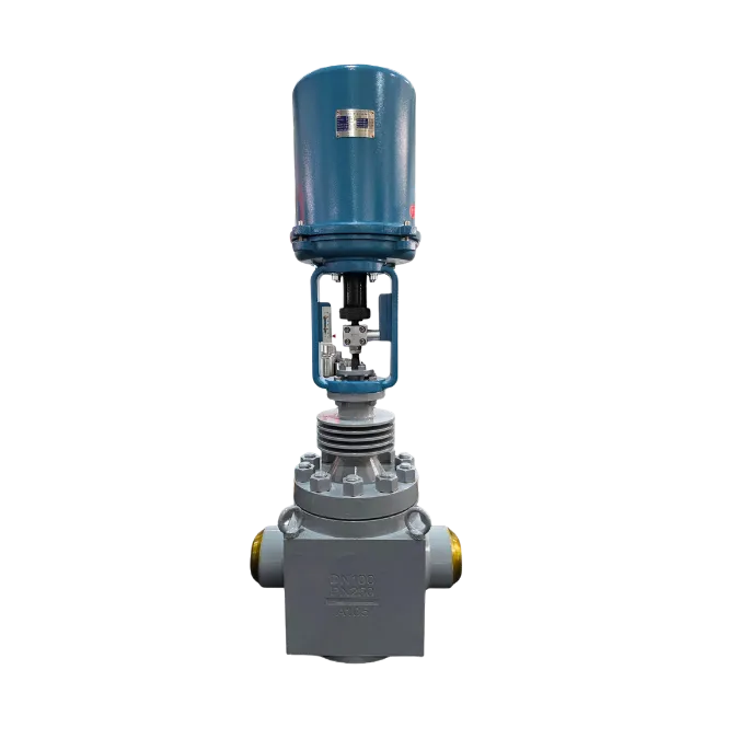
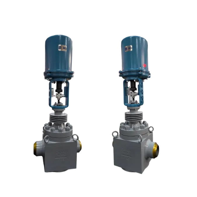
Product Overview
The 381LS series linear electric actuator converts an electrical command signal into controlled linear stem travel. It can be combined with globe valves and other compatible regulating valves through a selected mounting bracket and stem connection.
Product Advantages
The actuator package is configured around required thrust, speed, stroke, valve size, control signal and installation environment.
Reference basic error, hysteresis and dead zone are each controlled within the specified catalog limits for repeatable valve positioning.
Eight catalog models cover 800 N to 26,000 N with 30 mm, 60 mm or 100 mm maximum travel options.
Supports DC 4–20 mA or DC 1–5 V command signals and DC 4–20 mA output feedback.
AC and DC power options are available for different regions, control panels and industrial electrical standards.
Bracket codes A-2 through C-6 support multiple valve diameter ranges and stem-thread arrangements.
Main Technical Parameters
The following values are translated from the supplied actuator manual and should be confirmed for the final ordered model.
External Wiring
Use shielded cable for input and output signals. Do not route the power conductors and signal conductors in the same cable.
| Item | Standard S-Type Actuator |
|---|---|
| Power Cable | 3-core, 1.5 mm² |
| Signal Cable | 4-core, 1.5 mm² |
| Cable Entry | 2 × M20 × 1.5 |
Environmental Conditions
Confirm enclosure, heater and site conditions before selecting the actuator package.
| Condition | Standard S-Type Actuator |
|---|---|
| Temperature, No Heater | -10°C to 60°C |
| Temperature, With Heater | -35°C to 60°C |
| Relative Humidity | ≤ 95% |
| Ambient Gas | Non-corrosive gas |
| Mechanical Vibration | ≤ 1.5 g |
Series Selection
Select the actuator according to required thrust, operating speed, valve travel and shutoff force.
| Model | Output Thrust (N) | Operating Speed (mm/s) | Maximum Stroke (mm) |
|---|---|---|---|
| 381LSA-08 | 800 | 4.2 | 30 |
| 381LSA-20 | 2,000 | 2.1 | 30 |
| 381LSB-30 | 3,000 | 3.5 | 60 |
| 381LSB-50 | 5,000 | 1.7 | 60 |
| 381LSC-65 | 6,500 | 2.8 | 100 |
| 381LSC-99 | 10,000 | 2.0 | 100 |
| 381LSC-160 | 16,000 | 1.0 | 100 |
| 381LSC-260 | 26,000 | 1.0 | 100 |
Verify that actuator thrust is sufficient for valve shutoff differential pressure, packing friction and required safety margin.
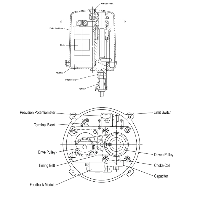
Actuator Drawings
Two drawing panels are retained to separate the A/B actuator body from the larger C-series configuration. Replace the URLs with final English engineering drawings.

Overall Dimensions
Dimension symbols correspond to the actuator outline drawings. Values are in millimetres unless otherwise stated.
| Model | D1 | D2 | H1 | h1 | h2 | d1 | d2 | d3 | C | K | M | W | Y | O | F | R | X | Weight (kg) |
|---|---|---|---|---|---|---|---|---|---|---|---|---|---|---|---|---|---|---|
| 381LSA | Ø225 | Ø260 | 200 | 78 | 18 | Ø90 | Ø70 | Ø55 | M14 × 1.5 | 15 | M8 | 28 | 87 | 10 | 12 | 80 | 75 | 12 |
| 381LSB | Ø255 | Ø290 | 280 | 125 | 31 | Ø125 | Ø102 | Ø70 | M18 × 1.5 | 18 | M10 | 45 | 90 | 10 | 15 | 100 | 91 | 22 |
| 381LSC | Ø310 | Ø360 | 415 | 175 | 31 | Ø150 | Ø125 | Ø85 | M22 × 1.5 | 24 | M12 | — | 90 | 10 | 15 | 160 | 120 | 55 |
Dimension W is not specified for the 381LSC row in the supplied catalog image. Confirm the final approved production drawing before manufacturing the mounting structure.
Mounting Brackets
Each actuator model may be paired with two or three bracket sizes according to the connected control-valve diameter. Always verify actuator thrust against valve opening and closing force.
| Actuator Model | Control Valve Diameter (DN) | Bracket Code |
|---|---|---|
| 381LSA-08 | 20 | A-2 |
| 381LSA-20 | 20–50 | A-2 |
| 381LSB-30 | 25–50 | B-3 |
| 381LSB-30 | 65–100 | B-4 |
| 381LSB-50 | 25–50 | B-3 |
| 381LSB-50 | 65–100 | B-4 |
| 381LSB-50 | 125–150 | B-5 |
| 381LSC-65 | 65–100 | C-4 |
| 381LSC-65 | 125–200 | C-5 |
| 381LSC-99 | 125–200 | C-5 |
| 381LSC-99 | 250–300 | C-6 |
| 381LSC-160 | 125–200 | C-5 |
| 381LSC-260 | 125–200 | C-5 |
| 381LSC-400 | 250–300 | C-6 |
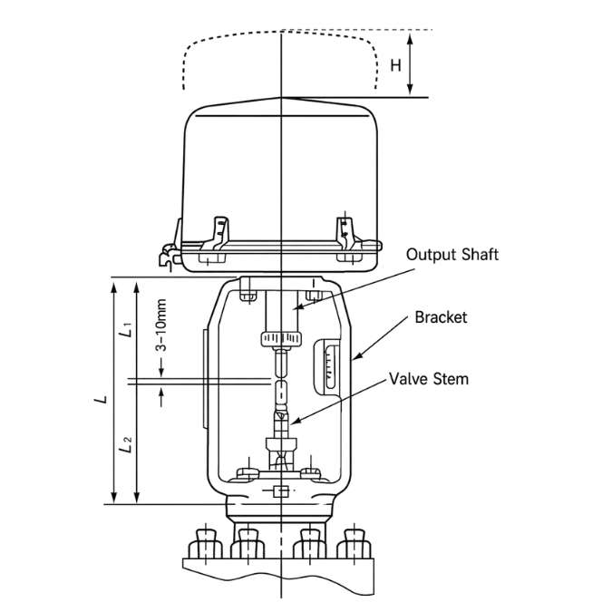
| Bracket Code | L | L1 | D | n-d1 | D2 | H | D3 | L2 |
|---|---|---|---|---|---|---|---|---|
| A-2 | 173 | 78 | Ø80 | 4-Ø10 | Ø60 | 130 | 100 | 17 |
| B-3 | 215 | 125 | Ø80 | 4-Ø10 | Ø60 | 157 | 125 | 21 |
| B-4 | 255 | 125 | Ø105 | 4-Ø12 | Ø80 | 175 | 135 | 21 |
| B-5 | 267 | 125 | Ø118 | 4-Ø14 | Ø95 | 177 | 155 | 25 |
| C-4 | 285 | 175 | Ø105 | 4-Ø12 | Ø80 | 205 | 155 | 27 |
| C-5 | 310 | 175 | Ø118 | 4-Ø14 | Ø95 | 210 | 155 | 27 |
| C-6 | 345 | 175 | Ø130 | 4-Ø18 | Ø100 | 220 | 175 | 27 |
| Control Valve Diameter (DN) | Reference L | Valve Stem Thread |
|---|---|---|
| 20, 25, 32, 40, 50 | 95 | M8 |
| 65, 80, 100 | 135 | M12 × 1.25 |
| 125, 150, 200 | 140 | M16 × 1.5 |
| 250, 300 | 170 | M20 × 1.5 |
Typical Applications
The package is suitable for automated flow, pressure, temperature and level control where controlled linear valve travel is required.

Selection Guide
Match actuator thrust, travel and speed to the connected valve and process-control requirements.
Confirm differential pressure, valve unbalance force, packing friction and shutoff requirement.
Match maximum actuator travel to the connected valve stem movement and adjustment range.
Confirm DC 4–20 mA or DC 1–5 V command signal and required output feedback.
Select the correct AC or DC supply and confirm the power requirements of actuator type A, B or C.
Confirm actuator model, valve diameter, bracket code, stem thread and installation dimensions.
Ordering Information
Complete operating and mechanical data helps determine the correct actuator, bracket, stem connector and control package.
Send the valve size, required thrust, stroke, supply voltage, control signal, mounting dimensions and operating conditions for a suitable quotation and drawing.