


Industrial Valve Automation
How Does an Actuator Valve Work? Electric and Pneumatic Valve Technologies Explained
In modern industrial automation, the actuator valve is one of the most important components for controlling liquid, gas, steam, and process media. Whether used in water treatment, chemical processing, oil and gas, HVAC systems, food production, power generation, or pharmaceutical manufacturing, an actuator valve allows a pipeline system to open, close, throttle, isolate, or regulate flow without constant manual operation.
1. Basic Structure of an Actuator Valve
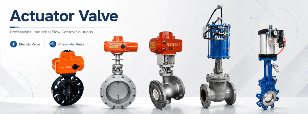
A complete actuator valve assembly normally consists of three main parts: the valve body, the actuator, and the control accessories. The valve body is the pressure-containing component installed in the pipeline. It may be a ball valve, butterfly valve, gate valve, globe valve, plug valve, diaphragm valve, or control valve. The actuator is mounted above or beside the valve and produces linear or rotary motion.
The control accessories may include positioners, limit switches, solenoid valves, manual overrides, feedback sensors, communication modules, air filter regulators, or local control panels. These accessories allow the actuator valve to communicate with a PLC, DCS, SCADA system, or local control station.
The operating principle depends on the type of valve. A ball valve and butterfly valve usually require a quarter-turn movement of 90 degrees. A gate valve or globe valve typically requires linear movement, meaning the stem travels up and down to open or close the flow path.
In a well-designed actuator valve system, the actuator must overcome valve friction, media pressure, seat load, stem packing resistance, and safety margin requirements. Engineers usually select an actuator with a torque or thrust safety factor of approximately 1.25 to 1.5 times the calculated valve operating requirement. In demanding services such as high-pressure steam, slurry, viscous fluid, or emergency shutdown systems, an even higher margin may be applied.
2. How an Actuator Valve Works Step by Step
The working process begins with a control signal. In an automated plant, this signal may come from a PLC, DCS, temperature controller, pressure transmitter, flow meter, or manual control station. The signal tells the actuator whether the valve should open, close, or move to a specific intermediate position.
For an on-off actuator valve, the command is simple: fully open or fully close. For a modulating control valve, the actuator receives a proportional control signal, commonly 4–20 mA, 0–10 V, or a digital communication command. The actuator then moves the valve to the required position, such as 25%, 50%, 75%, or any defined opening percentage.
Once the actuator receives the command, it converts energy into motion. In an electric valve, an electric motor drives a gear train, which rotates or pushes the valve stem. In a pneumatic valve, compressed air enters an actuator chamber and moves a piston, diaphragm, or rack-and-pinion mechanism. This mechanical movement changes the internal flow path of the valve.
When the valve reaches the required position, a feedback device confirms the position to the control system. Limit switches confirm fully open or fully closed status, while position transmitters provide continuous feedback. This feedback is important for safety, process stability, predictive maintenance, and remote monitoring.
3. Electric Valve: Working Principle and Technical Features
An electric valve uses an electric actuator to automate valve operation. The actuator generally contains a motor, gear reducer, drive shaft, torque switches, limit switches, control board, and sometimes a manual handwheel. When electrical power is supplied, the motor rotates. The gear reducer lowers the speed and increases the output torque. The final output shaft then moves the valve to the desired position.
Electric actuators are commonly available in voltages such as 24 V DC, 110 V AC, 220 V AC, 230 V AC, and 380 V AC. Small electric valve units may produce only a few newton-meters of torque, while heavy-duty industrial actuators can deliver thousands or even tens of thousands of newton-meters.
Operating times vary widely. A small quarter-turn electric valve may complete a 90-degree movement in 5 to 15 seconds, while a large multi-turn actuator for a gate valve may require 30 to 120 seconds or more.
24 V DC, 110 V AC, 220/230 V AC, 380 V AC
5–120 seconds depending on valve size and actuator type
On-off, 4–20 mA, 0–10 V, digital bus communication
IP65, IP67, IP68, explosion-proof options
Advantages of Electric Valves
The main advantage of an electric valve is control precision. Because electric actuators can use motor feedback, encoders, torque sensors, and digital control boards, they are well suited for applications requiring accurate positioning. Electric valves also simplify installation when compressed air infrastructure is not available.
Another advantage is energy efficiency during holding position. Many electric actuators consume power mainly during movement. Once the valve reaches the target position, mechanical gearing or braking can hold the valve without continuous power consumption.
Electric valves are also easy to integrate into intelligent automation platforms. They can provide detailed diagnostic data, including valve stroke count, torque trend, travel time, motor temperature, fault history, and communication status.
Limitations of Electric Valves
Despite their advantages, electric valves have some limitations. Their response speed is usually slower than pneumatic valves, especially in emergency shutdown applications. Electric actuators may also be sensitive to moisture, vibration, high temperature, or hazardous environments if not properly protected.
Electric actuators are often more complex internally than pneumatic actuators. The motor, gearbox, control board, wiring, and electronic components must be maintained correctly. In high-cycle applications where the valve opens and closes very frequently, motor heating and gearbox wear must be considered.
4. Pneumatic Valve: Working Principle and Technical Features
A pneumatic valve uses compressed air as the power source. The most common pneumatic actuator designs include rack-and-pinion actuators, scotch-yoke actuators, piston actuators, and diaphragm actuators. When compressed air enters the actuator, it creates force on a piston or diaphragm. This force is converted into rotary or linear motion, which moves the valve.
Industrial pneumatic systems usually operate at air supply pressures of approximately 4 to 7 bar, although some systems may work within a broader range of 3 to 8 bar. The actuator output torque or thrust depends on air pressure, piston area, spring force, and mechanical design.
Pneumatic valves are often used where fast response, simple construction, high cycle life, and fail-safe operation are required. A spring-return pneumatic actuator can automatically move the valve to a predefined safe position when air pressure is lost.
3–8 bar, commonly 4–7 bar in industrial systems
Less than 1 second to several seconds depending on size
Rack-and-pinion, scotch-yoke, piston, diaphragm
Spring return: fail open or fail closed
Advantages of Pneumatic Valves
The pneumatic valve is known for fast operation and rugged reliability. Because compressed air can move actuator pistons quickly, pneumatic valves are widely used in production lines, packaging equipment, chemical plants, refineries, and emergency isolation systems.
Pneumatic actuators are also mechanically simple. They contain fewer electronic parts and can tolerate harsh industrial conditions when properly specified. Their structure is suitable for frequent cycling, and they can operate reliably in dusty, humid, or vibrating environments.
Safety is another major advantage. A spring-return pneumatic actuator can be designed to fail closed, fail open, or fail in place depending on process requirements. For example, a fuel gas valve may fail closed to stop gas flow during an emergency, while a cooling water valve may fail open to protect equipment from overheating.
Limitations of Pneumatic Valves
The main limitation of a pneumatic valve is its dependence on compressed air infrastructure. Air compressors, dryers, filters, regulators, tubing, fittings, and maintenance procedures are required. Poor air quality can cause actuator sticking, corrosion, seal wear, or unstable positioning.
Pneumatic control can also be less precise than electric control unless a high-quality positioner is installed. For accurate modulation, the pneumatic valve usually requires an electro-pneumatic positioner that converts a 4–20 mA signal into air pressure control.
5. Electric Valve vs Pneumatic Valve: Technical Comparison
Selecting between an electric valve and a pneumatic valve depends on process requirements, site infrastructure, safety philosophy, control precision, operating speed, installation cost, and maintenance resources. Neither technology is universally superior. Each one is optimal under different conditions.
| Parameter | Electric Valve | Pneumatic Valve |
|---|---|---|
| Power Source | Electricity: AC or DC power | Compressed air, usually 3–8 bar |
| Speed | Moderate; commonly 5–120 seconds | Fast; often less than 1 second to several seconds |
| Control Accuracy | High, especially with digital feedback | Medium to high with positioner |
| Installation | Requires power and signal wiring | Requires air supply, tubing, solenoid valve, and accessories |
| Fail-Safe Function | Requires battery, spring return, or special design | Simple and reliable with spring-return actuator |
| Maintenance | Motor, gearbox, switches, electronics | Air quality, seals, solenoid valve, actuator lubrication |
| Best Applications | Water systems, HVAC, remote control, precise positioning | Fast cycling, emergency shutdown, hazardous areas, process plants |
6. Key Engineering Data for Actuator Valve Selection
Correct selection is essential for long-term performance. Engineers normally evaluate valve size, pressure rating, medium type, temperature, required torque, control mode, power supply, environmental protection, safety position, and communication requirements. A DN50 actuator valve used in a clean water system has very different requirements from a DN300 butterfly valve used in a corrosive chemical process.
Torque is one of the most important parameters. If the actuator torque is too low, the valve may fail to open or close fully. If the actuator is oversized without proper control, it may damage the valve stem, seat, or gearbox.
A practical method is to calculate the maximum valve torque under operating pressure and then apply a suitable safety factor. For clean media and normal service, 25% to 50% additional torque is commonly used. For steam, slurry, or sticky media, higher margins may be required.
Cycle frequency is another important factor. A valve that operates once per day can use a different actuator design from a valve that cycles thousands of times per month. Pneumatic actuators are often preferred for high-cycle applications because of their simple construction and rapid movement.
7. Typical Applications of Actuator Valves
In water treatment plants, actuator valves are used for pump control, filtration systems, chemical dosing, sludge handling, and distribution networks. Electric valves are common in these systems because they are easy to integrate with remote monitoring and SCADA platforms.
In chemical and petrochemical plants, pneumatic valves are widely used because they offer fast response, strong safety functions, and good compatibility with hazardous area requirements. Emergency shutdown valves, tank isolation valves, reactor feed valves, and process control valves often use pneumatic actuators.
In HVAC and building automation, electric valves are used to regulate chilled water, hot water, steam, and air handling systems. Their accurate control helps improve energy efficiency and indoor comfort.
In food and beverage production, actuator valves support hygienic processing, cleaning-in-place systems, filling lines, and automated batching. In power plants, actuator valves control boiler feedwater, cooling water, steam distribution, fuel systems, and auxiliary processes.
8. How to Choose the Right Actuator Valve
The first step is to define the valve function. If the application only requires open and close operation, an on-off actuator valve is usually sufficient. If the process requires flow, pressure, or temperature regulation, a modulating actuator with position feedback is necessary.
The second step is to evaluate available power sources. If the site already has a reliable compressed air system, a pneumatic valve may be economical and fast. If compressed air is unavailable or expensive to maintain, an electric valve may be the better choice.
The third step is to consider safety behavior. If the valve must move automatically to a safe position during power or air failure, pneumatic spring-return technology is often the simplest solution. Electric actuators can also provide fail-safe operation, but they may require batteries, capacitors, mechanical springs, or dedicated emergency power systems.
The fourth step is to consider control precision and diagnostics. If the plant requires accurate positioning, digital communication, maintenance data, and remote diagnostics, an intelligent electric valve can provide significant value. If the plant requires fast and robust operation with simple fail-safe logic, a pneumatic valve may be more suitable.
9. Future Trends in Actuator Valve Technology
Actuator valve technology is becoming more intelligent, connected, and energy efficient. Electric actuators are increasingly equipped with digital sensors, self-calibration, predictive maintenance algorithms, and industrial Ethernet communication.
Pneumatic valve systems are also improving. Modern pneumatic positioners can provide high accuracy, low air consumption, advanced diagnostics, and digital communication. Low-friction seals, improved spring designs, and corrosion-resistant materials are extending service life in harsh environments.
Another trend is the integration of actuator valves into Industrial Internet of Things platforms. Instead of treating valves as simple mechanical devices, modern plants increasingly view them as data-generating assets. Information such as cycle count, travel deviation, control signal response, air pressure stability, motor current, and valve torque trend can help maintenance teams predict failure before it occurs.
Conclusion
An actuator valve works by converting electrical or pneumatic energy into mechanical motion that controls the opening position of a valve. The electric valve offers strong positioning accuracy, intelligent diagnostics, and convenient integration with digital control systems. The pneumatic valve provides fast response, rugged construction, high cycle capability, and reliable fail-safe operation.
For applications requiring precise control, remote monitoring, and simple electrical installation, the electric valve is often the preferred solution. For applications requiring rapid movement, emergency shutdown, hazardous-area compatibility, and spring-return safety, the pneumatic valve remains a highly effective choice. By understanding how each actuator valve works and comparing the technical data carefully, engineers can select a valve automation solution that improves safety, efficiency, and long-term process reliability.