


Match the valve to process function, media, pressure and service conditions.
Fleyenda Flow Technology / Water & Wastewater
Water Treatment Valves for Equipment Manufacturers
Engineered valve and actuator solutions for filtration packages, reverse osmosis skids, chemical dosing units, industrial wastewater equipment and packaged pumping systems. Built around your process duty, control philosophy and repeatable equipment BOM.
Electric & pneumatic assembliesMaterials & sealing selectionTechnical documentation
Common equipment interfaces
RO feed, concentrate & CIP
Filtration & automatic backwash
Chemical dosing & neutralization
Sludge, pumps & wastewater lines
Valve, actuator and feedback accessories evaluated as a single assembly.
Dimensional coordination and inspection requirements for technical approval.
Part identification and controlled specifications for equipment build programs.
The equipment-builder perspective
A Valve Is a Functional Part of the Entire Treatment System
For an OEM or EPC contractor, selecting industrial water treatment valves is not just a matter of matching DN and pressure rating. The selected valve affects pressure loss, equipment footprint, cleaning access, electrical integration, maintenance procedures and downstream protection.
Fleyenda works with water treatment equipment manufacturers and system integrators to define isolation, diversion, non-return and control duties across the full equipment package. The goal is an appropriate valve specification that can be repeated across units, documented for approval and maintained in the field.
Confirm filtration, dosing, membrane cleaning or sludge conditions before choosing valve construction.
Consider envelope dimensions, actuator orientation, power supply and maintenance access early.
Align project BOMs, drawings, approved models, inspection points and spares.
01 / Electric valve portfolio
Electric Valves for Water Treatment Equipment
Three essential automated duties for water treatment OEMs: isolate the line, route the flow, or modulate the process. Select the operating function before confirming body and seat materials, installation dimensions, pressure ratings and actuator signals.
01 / Isolation & backwashFLE-D-CEF
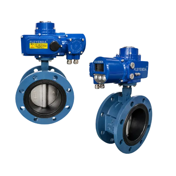
Automated shutoff
Electric Flanged Butterfly Valve
For automatic isolation, filter backwash sequencing and water-distribution lines. Compact face-to-face installation with electric operation. Verify seat compatibility, pressure differential and actuator torque.
- DN50–DN600
- PN10 / PN16
- Flanged / EPDM option
02 / Flow diversionFLE-Q-TF
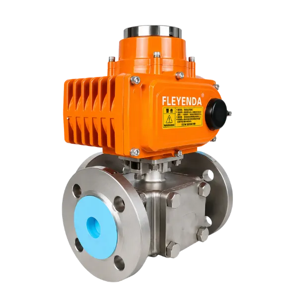
Automated flow routing
Electric 3-Way Flanged Ball Valve
Switch between filters, bypass lines or process branches with L-port or T-port configurations. Confirm port connections in every actuator position before selecting controls and fail position.
- DN15–DN200
- L-Port / T-Port
- On/Off electric
03 / Flow regulationFLE-VQ-F
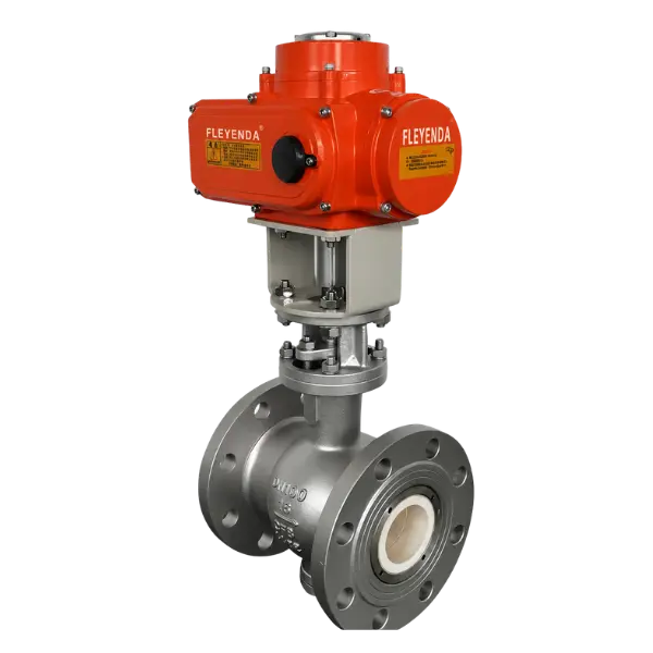
Proportional process control
Electric V-Port Control Valve
For selected water and process-liquid loops requiring repeatable throttling rather than simple switching. Size the V-port using flow range, differential pressure, Cv and control signal.
- DN25–DN300
- V-Port segmented
- Modulating options
Additional Valve Types for Specialized Treatment Duties
Small-bore chemical lines, abrasive wastewater and pneumatic packages often need a different valve construction from main water-line automation.
UPVC Electric Ball Valves
Compact automated isolation for compatible low-temperature water and chemical lines. Confirm pressure derating, polymer compatibility, sealing and true-union access.
View ProductPneumatic PVC Ball Valves
Fast on/off actuation for appropriate dosing and auxiliary lines. Check instrument air, spring return requirements and medium compatibility.
View ProductPneumatic Knife Gate Valves
Selected wastewater sludge duties with suspended solids. Review solids content, differential pressure, gate seal design and cycling requirements.
View Product02 / Equipment applications
Where Valves Add Value Inside a Treatment Package
The appropriate valve depends on its location and failure consequences within the process, not simply on whether the project is called "water treatment" or "wastewater treatment".
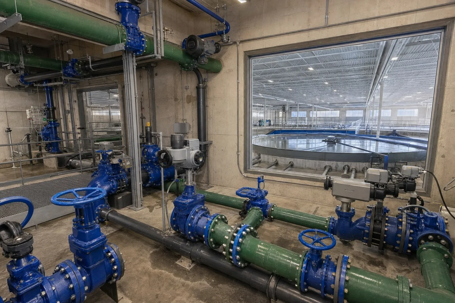
Main engineering focus / Reverse osmosis
Valves for RO Skids, Membrane Systems & CIP Lines
An RO package includes multiple operating states: production, shutdown, flushing and chemical cleaning. Isolation and non-return functions should be coordinated with the high-pressure pump, membrane vessels and automatic sequence.
- Feed & pumpIsolation, check-valve behavior and upstream pressure limits.
- ConcentratePressure control, brine chemistry and designed pressure drop.
- PermeateIsolation, backflow prevention and hygiene requirements.
- CIP / flushingCleaning chemical compatibility and reliable path segregation.
Filter & Backwash Packages
Rapid and repeatable switch-over between filtration, backwash, rinse and drain states. Compare valve operating time, cycle frequency, head loss and actuator feedback in the sequencing logic.
Valve duties: butterfly / ball / check
Chemical Dosing Skids
Acids, alkalis, coagulants and cleaning agents require verified wetted-material compatibility. Review chemical concentration, temperature, pressure, permeation and the ability to service true-union connections.
Valve duties: plastic / lined ball / diaphragm
Tratamiento de aguas residuales
Influent, effluent and process water normally differ from sludge and grit streams. Specify knife gates only where their construction is appropriate for the solids loading and pressure differential.
Valve duties: butterfly / check / knife gate
Booster & Transfer Skids
Pump sets need maintainable isolation and non-return behavior during starts, trips and parallel operation. Assess static head, minimum flow and transient pressure rather than treating a check valve as a generic commodity.
Valve duties: check / butterfly / ball
Desalination & Brine Lines
Seawater and concentrated brine call for careful evaluation of chloride exposure, crevice corrosion, elastomer compatibility and the full pressure-temperature envelope. Material selection is project-specific.
Valve duties: corrosion-resistant isolation / control
Utilities, Drains & Sampling
Compact valves on drain, vent, bypass and sampling branches can affect maintainability and operator safety. Review access clearance, dead legs, isolation policy and line identification.
Valve duties: compact ball / check / specialty
03 / System-level engineering
Typical Valve Positions in an RO Equipment Train
Use the process sequence to build a valve list. A functional drawing identifies duties; final sizing and approval require actual P&IDs and design conditions.
Feedwater
Inlet isolation and diversion to pretreatment equipment.
Ball / butterflyPrefiltration
Isolation and automatic filter backwash or rinse paths.
Butterfly / ballHigh-pressure pump
Discharge protection, maintenance isolation and transient review.
Check / isolationRO membranes
Feed, reject, product routing and selected pressure regulation.
Isolation / controlCIP & discharge
Cleaning-fluid path selection, rinse and safe drainage.
Compatible ball / diaphragmOne skid, several valve specifications.
Consider normal production, emergency shutdown, pump trip, maintenance isolation and chemical cleaning as separate operating cases. The fail position and leakage class should be agreed for each actuated valve.
04 / Quick selection reference
Water Treatment Valve Selection by Process Duty
A practical first-pass reference for OEM specification discussions. Final model selection should follow verified fluid data, piping conditions and the project's approved engineering standards.
| Process duty | Starting valve type | Why it may fit | Critical engineering check | Product path |
|---|---|---|---|---|
| Filter feed / backwash | Actuated butterfly or ball | Compact sequencing and remote switching | Valve travel time, pressure drop, cycles, seat compatibility | Electric butterfly valve |
| RO pump discharge | Check valve plus isolation | Reverse-flow protection after pump trip | Closure dynamics, minimum flow, water hammer, orientation | Check valve guide |
| RO CIP / flushing | Ball or diaphragm | Defined cleaning and flush paths | Chemical concentration, seal swelling, temperature and drainage | UPVC electric ball |
| Chemical dosing | Compatible plastic / lined valve | Isolation of selected chemical lines | Wetted-material data, pressure derating and chemical service | Pneumatic PVC ball |
| Sludge transfer | Knife gate / appropriate solids valve | Isolation in selected solids-bearing streams | Solids size, abrasion, solids settling, differential pressure | Pneumatic knife gate |
| Process flow modulation | Control / characterized V-port | Adjustment of flow or pressure where applicable | Cv/Kv, cavitation, control range, actuator sizing | Control-capable ball valves |
| Desalination / brine | Application-specific isolation | Materials selected for corrosive process service | Chlorides, crevice corrosion, pressure, temperature, deposits | Actuated valves |
Importante: Selection tables are guidance, not a substitute for material compatibility data, application-specific safety reviews, supplier-approved datasheets or applicable potable-water approvals.
For OEM quotations: Send a P&ID or valve schedule when available so that each valve position can be checked against the actual process function.
05 / Materials & chemical service
Choosing Valve Materials for Different Water Chemistries
There is no universally “best” valve material for water treatment. The right choice changes between filtered water, corrosive dosing chemicals, high-chloride streams, wastewater solids and cleaning circuits.
| Service condition | Construction to evaluate | Important limitation | Data needed for approval |
|---|---|---|---|
| General filtered water | Appropriate coated iron, stainless steel or suitable thermoplastics with compatible seats | Water chemistry, coating damage and elastomer suitability can affect durability. | pH, temperature, pressure, chlorides, potable-water requirements |
| Acid / alkali dosing | Selected UPVC, CPVC, PP, PVDF, PTFE-lined or specialty constructions | Compatibility varies with chemical identity, concentration and operating temperature. | Exact chemical, wt%, temperature, pressure, seal composition |
| Oxidizing disinfectant | Chemical-service materials selected from verified wetted-material data | Oxidizers may attack certain elastomers, plastics or metal alloys even when diluted. | Concentration, pH, exposure duration, temperature, cleaning regimen |
| RO cleaning / CIP | Compatible ball, diaphragm or specialty isolation arrangements | Cleaning chemistry and thermal exposure may differ from routine production conditions. | CIP chemicals, maximum cleaning temperature, exposure time |
| Seawater / concentrate | Suitable high-corrosion-resistance metallic, polymeric or lined solutions | Do not presume an ordinary stainless grade is immune to chloride attack. | Chlorides, oxygen, pressure, temperature, deposits, service life |
| Sludge / suspended solids | Knife gate, butterfly or abrasion-oriented valve construction as appropriate | Seating design, sediment accumulation and erosion may dominate material life. | Solid fraction, particle size, abrasiveness, operating cycles |
Elastomer check: EPDM, NBR and FKM have different compatibility profiles. A PTFE seat may be appropriate for some chemicals, but gaskets, stem seals and end connections must also be checked.
Approval approach: Confirm materials using current supplier compatibility data and the exact process conditions—not a generic list of “acid-resistant” or “corrosion-resistant” valves.
06 / Engineering knowledge
Critical Decisions Before Approving a Valve
Design errors often appear at the interface between process conditions, mechanical fit and control hardware. The most useful supplier discussion happens before the equipment BOM and electrical drawings are frozen.
Material Compatibility Is More Than "Corrosion Resistant"
Water chemistry can vary significantly across intake, pretreatment, RO, regeneration and dosing circuits. Confirm the complete wetted path—not only the body material.
- Record chemical identity, concentration, pH, chlorides, suspended solids and cleaning exposure.
- Verify body, trim, coating, seat, O-ring and seal compatibility together.
- Account for pressure-temperature derating in polymer valves and aggressive chemical mixtures.
- Specify required drinking-water or high-purity approvals separately where applicable.
Evaluate Pressure Drop and Transient Behavior
A nominal pressure class is not enough for valve selection. Head loss, differential pressure across the seat and transient events affect both valve and pump-system reliability.
- Check operating flow range, fluid density, design pressure and temperature.
- For throttling duties, calculate Cv/Kv and investigate cavitation or flashing risk.
- For check valves, consider startup, minimum velocity, pump trip and reverse-flow dynamics.
- Size actuators against the correct maximum seating and breakaway torque.
Make the Valve Fit the Complete Skid Layout
Dimensional mismatches become expensive when valves are fitted into compact machines or prefabricated manifolds. Confirm key interfaces early.
- Flange drilling, face-to-face length, union end type and pipe schedule.
- Actuator envelope, handwheel access, service clearance and cable-entry direction.
- Installation orientation, pipe support and accessibility for inspection.
- Repeatable dimensions for multi-skid manufacturing programs.
Specify What the Valve Must Do on Power Loss
On/off isolation, modulating control and emergency positioning require different specifications. The chosen fail position depends on the actual process hazard assessment.
- Define open/close versus modulating duty, travel time and duty cycle.
- Check power availability, instrument air quality and control system signals.
- Confirm limit switches, position indication and feedback to PLC/SCADA.
- Define loss-of-power and loss-of-air responses for each valve position.
Engineering principle
A single treatment system can require cast iron, stainless, thermoplastic and specially lined valve constructions in different positions. Choose each on proven service conditions rather than specifying one valve material for the entire plant.
07 / Automation integration
Electric or Pneumatic: Select an Actuator for the Duty
Actuated water treatment valves are components of the equipment control architecture. The actuator, switches, accessories, enclosure and fail strategy should be specified as a complete package, particularly for automatic backwash and remote process skids.
Electric Actuation
Useful where the equipment provides electrical power and PLC commands but instrument air may be unavailable. Review duty cycle, torque margin and weatherproofing.
- Control
- On/off or selected modulating arrangements
- Signals
- Discrete commands, feedback, selected 4–20 mA / 0–10 V
- Specify
- Voltage, travel time, enclosure and power-failure action
Pneumatic Actuation
Often selected for repetitive cycling and plants with a dependable compressed-air network. Verify air quality, pressure, solenoid arrangement and spring-return requirements.
- Control
- Double-acting or spring-return packages
- Signals
- Solenoid actuation, position switches, optional positioner
- Specify
- Air supply, accessories, stroke time and loss-of-air state
Manual & Hybrid Options
Not every valve position needs automation. Separate critical sequencing duties from occasional maintenance isolation to simplify cost, reliability and operating access.
- Control
- Manual lever, gearbox or selected override
- Operations
- Isolation, maintenance and controlled commissioning
- Specify
- Operator clearance, access and lockout requirements
08 / Water treatment project referenceRead the Water Treatment Project
Valve Selection for a Mexico Water Treatment Project
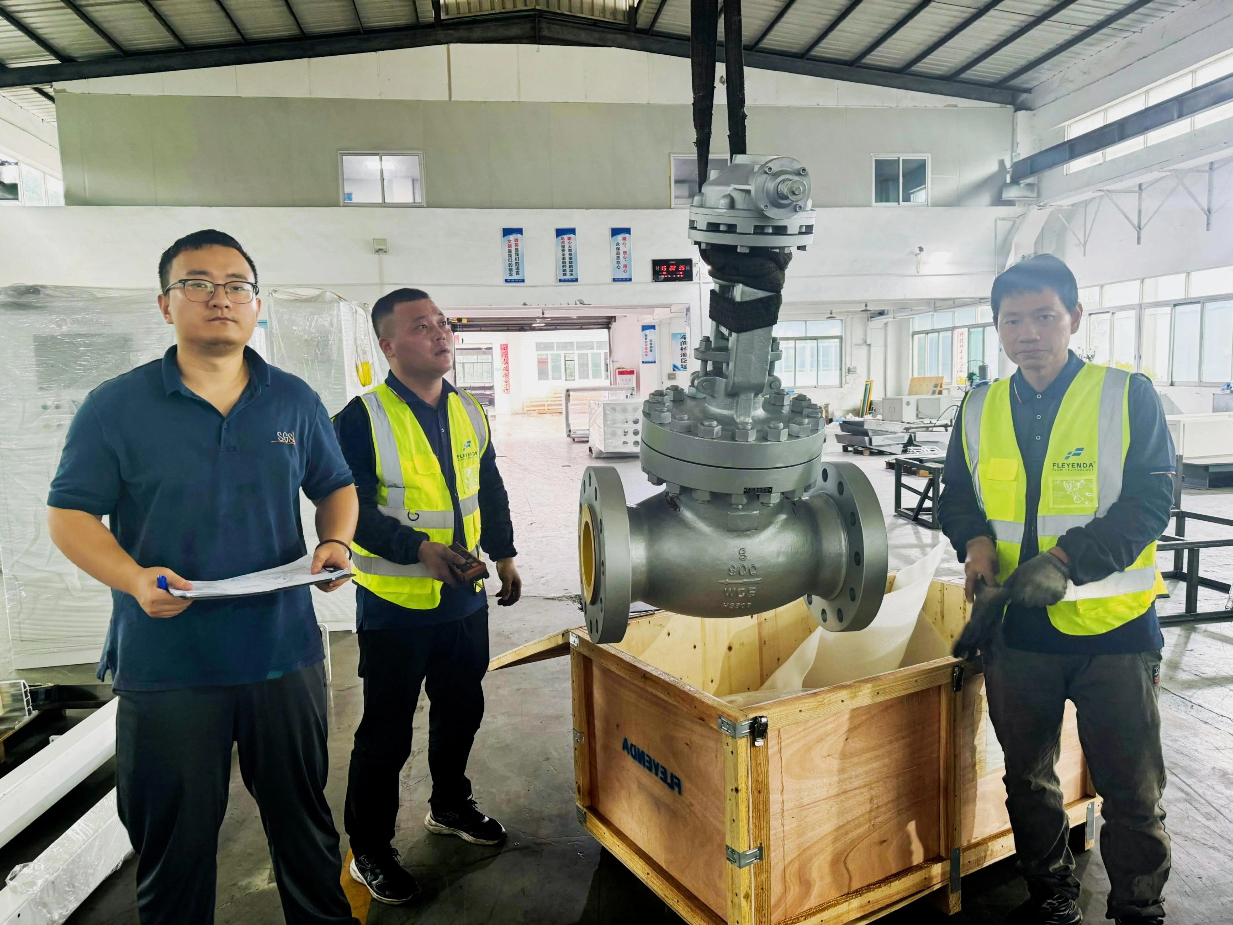
In a published water treatment project reference, Fleyenda describes working with a customer in Mexico to review large-diameter water-line operation, corrosion and humidity exposure, actuator integration and maintenance requirements.
ApplicationTratamiento y distribución de agua
Products discussedElectric butterfly & gate valves
Engineering prioritiesIsolation, actuator control and maintainability
CollaborationOn-site technical discussion
09 / Quality & project coordinationTechnical submittals Testing requirements Identification & BOM Project continuity
OEM Supply That Supports Engineering Approval
System integrators and machine builders need more than unit pricing. Valve procurement should support drawing approval, material control, inspection planning, predictable identification and maintenance across repeat installations.
Datasheets, dimensional drawings, valve/actuator interface details and requested electrical documentation.
Agree shell, seat-leakage, functional and inspection requirements using the applicable product standards and project ITP.
Align approved model references, quantities, end-connection specifications and customer part numbers.
Discuss spare parts, replacement access, revision control and repeat orders for series-built equipment.
10 / OEM procurement guide
What to Send for Accurate Valve Selection & Quotation
Sharing complete operating and interface information at the RFQ stage reduces rounds of clarification and lowers the risk of approving a valve that does not fit the machine.
Process Conditions
- Equipment type and P&ID line reference
- Fluid composition, concentrations, solids and chlorides
- Operating / design pressure and temperature
- Normal, minimum and maximum flow
- Isolation, non-return or modulating duty
Mechanical & Automation
- DN/NPS, piping material and connection standard
- Body, trim and sealing preferences
- Face-to-face and installation restrictions
- Power supply or instrument-air conditions
- Control signals, feedback and fail-state requirement
Supply & Approval
- Estimated quantity and equipment build schedule
- Destination market and project specifications
- Applicable test / inspection standards
- CAD, drawings, certificates or records required
- Spare-parts and repeat-order expectations
11 / Frequently asked questions
Engineering Questions About Water Treatment Valves
Answers below address common selection discussions. Final decisions depend on the actual equipment specification and approved product data.
Which valves are most often used in water treatment equipment?
Butterfly valves are common for larger isolation and filtration lines; ball valves for compact isolation, chemical-compatible connections and bypasses; check valves for non-return duties; knife gates for selected solids-bearing wastewater; and control valves where flow or pressure modulation is required. Select by specific duty rather than using the same valve throughout a treatment system.
What valve types should an RO skid builder consider?
RO systems typically require isolation at feed and utility branches, appropriate check-valve protection around pump circuits, and compatible valves for flushing and CIP. Concentrate control and any throttling duty require hydraulic sizing and an understanding of membrane design limits. The final P&ID determines the valve list.
Is a PVC or UPVC valve suitable for every chemical dosing line?
No. Thermoplastic suitability depends on the exact chemical and concentration, operating temperature, pressure, joint design and seal materials. Some media and temperatures require CPVC, PP, PVDF, lined metallic or other constructions. Check the approved compatibility data for every wetted component.
How should check valves be selected for pump discharge lines?
Confirm operating flow and velocity, static head, downstream line volume, pump stop characteristics, installation orientation and allowable transient pressure. Non-return behavior depends on valve design and dynamics, not only nominal bore and pressure class. Transient analysis may be required in surge-sensitive systems.
Can Fleyenda supply electric and pneumatic valve assemblies?
Fleyenda lists electric and pneumatic valve products with actuator options. For a specific package, provide the required voltage or air pressure, torque duty, cycle frequency, position feedback, enclosure rating, control signals and desired safe position so the configuration can be reviewed.
Which documents should be requested for an OEM water treatment valve package?
Common submittals include approved datasheets, valve and actuator drawings, material information, wiring or pneumatic schematics, inspection and test scope, identification details and installation instructions. Project-specific compliance documentation should be agreed before ordering.
How do you select valve materials for seawater and brine?
Review chloride concentration, oxygen, crevice geometry, deposits, pressure and temperature, cleaning chemicals and expected maintenance conditions. Do not assume that a generic stainless-steel grade is automatically suitable for high-chloride service. Materials need case-by-case evaluation.
Build your next treatment equipment package
Need Water Treatment Valves for an OEM Project?
Send us your valve schedule, P&ID, media data or equipment application. We can discuss suitable valve types, connection standards, material options, automation interfaces and requested documentation.