


ENGINEERING KNOWLEDGE / VALVE MAINTENANCE
Why Do Electric Actuated Ball Valves Fail? 8 Common Problems & Fixes
Electric Actuated Ball Valves are widely used in industrial pipelines for automated shutoff, remote operation and fluid control. However, electrical faults, mechanical wear, incorrect actuator sizing and unsuitable operating conditions can affect valve performance over time.
Understanding the causes of failure is essential for maintenance engineers, equipment manufacturers and industrial buyers. This guide examines eight common electric actuated ball valve problems, explains how to diagnose them, and provides practical solutions to improve equipment reliability and reduce unplanned downtime.
FLEYENDA / PRODUCT SOLUTIONS
Electric Actuated Ball Valve Replacement Solutions
Select a suitable valve and actuator configuration according to your pipeline conditions, operating requirements and automation system.
QUARTER-TURN ELECTRIC ACTUATION
Electric 2-Way Flanged Ball Valve
Designed for automated pipeline isolation and remote operation, the FLE-Q-F combines a flanged ball valve with an electric actuator. Its quarter-turn design supports integration with industrial control systems and centralized automation equipment.
Conexión con bridas
Electric Operation
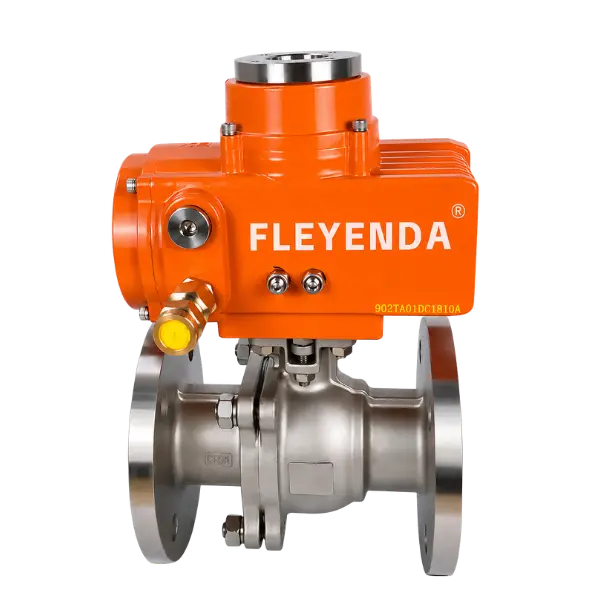
FLE-Q-F / ELECTRIC 2-WAY FLANGED BALL VALVE
TECHNICAL SPECIFICATIONS
1/2″–12″ / DN15–DN300
PN16–PN40 / ANSI Class 150–300
de −20 °C a +180 °C
SS304 / SS316 / WCB
ANSI / DIN / JIS Flanged
Electric Quarter-Turn, 0–90°
Final specifications depend on the selected valve and actuator configuration. Confirm operating pressure, differential pressure, temperature, medium compatibility, required torque and control function before ordering.
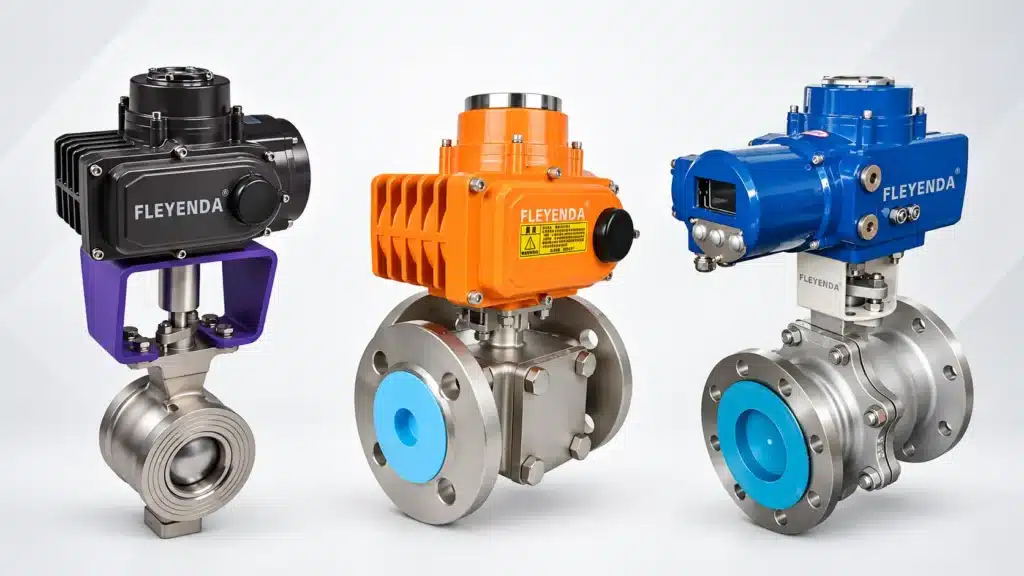
Why Do Electric Actuated Ball Valves Fail?
An electric actuated ball valve consists of several interconnected components, including the valve body, ball, stem, seats, actuator motor, gearbox and electrical control system. A fault in any of these components can affect the performance of the complete assembly.
For example, a valve that does not open may have an electrical supply problem, an incorrectly configured control circuit or a mechanically blocked ball. Replacing the actuator without checking the valve’s operating torque may not solve the problem.
Understanding the relationship between the actuator, valve mechanism and process conditions is therefore essential for accurate troubleshooting.
| Observed Problem | Possible Cause | First Diagnostic Check |
|---|---|---|
| Actuator does not respond | Power supply, fuse, wiring or control fault | Verify rated voltage and control circuit |
| Motor runs but valve does not move | Coupling, gearbox, stem or mechanical damage | Check manual operation and drive connection |
| Valve cannot fully open or close | Incorrect travel limit or mechanical obstruction | Inspect limit switches and valve travel |
| Actuator stops during travel | Excessive torque or overload protection | Compare valve torque requirement with actuator output |
| Valve leaks when closed | Damaged seat, contamination or incomplete closure | Inspect shutoff condition and seat compatibility |
| External leakage | Stem seal, body gasket or flange connection damage | Locate the leakage source |
| Actuator overheats | Excessive cycling, wrong voltage or mechanical overload | Check duty cycle, supply and valve torque |
| Incorrect position feedback | Limit switch, feedback circuit or signal configuration fault | Compare commanded and actual position |
1. Electric Actuator Does Not Respond
One of the most common problems with electric actuated ball valves is a complete lack of response after an open or close command. The actuator may show no indication, produce no motor sound or fail to move when controlled from a PLC or local control station.
Posibles causas
- No electrical power reaching the actuator.
- Incorrect supply voltage compared with the actuator nameplate.
- Blown fuse or tripped circuit breaker.
- Loose, disconnected or incorrectly connected wiring.
- Emergency stop or control interlock preventing operation.
- Local/remote selector or control input incorrectly configured.
- Thermal protection or overload protection has been activated.
How to Troubleshoot
Start by checking the power supply and confirming that the voltage matches the actuator nameplate. An actuator designed for DC24V should not be connected to an AC220V supply.
Next, inspect the control circuit, terminal connections, fuse and circuit breaker. If the valve is controlled remotely, verify that the PLC output or relay is delivering the correct command and that no interlock is preventing movement.
Check the actuator’s status indicators and fault signals, if available. If the power supply and external control circuit are correct but the motor still does not operate, the internal motor, capacitor, control board or protective circuit may require inspection by qualified personnel.
Prevention: Confirm the electrical supply, wiring diagram, cable specification and control logic before commissioning. For actuator voltage and configuration selection, see Fleyenda’s FLE Series Electric Actuator.

2. The Actuator Motor Runs but the Ball Valve Does Not Move
If the motor can be heard running but the valve does not rotate, the problem may be located in the mechanical connection between the actuator and valve body.
Posibles causas
- Damaged or disconnected actuator-to-valve coupling.
- Incorrect mounting or misalignment between actuator and valve stem.
- Broken or worn internal gear components.
- Damaged valve stem or drive key.
- Foreign material or deposits blocking ball movement.
- Valve seats have swollen, deteriorated or developed excessive friction.
How to Troubleshoot
First, check whether the actuator mounting bracket and drive connection are properly installed. The actuator output must engage the valve stem correctly. A loose coupling or incorrectly fitted adapter may allow the motor to run without transmitting sufficient torque to the ball.
If the manufacturer provides a manual override, follow its instructions to check whether the valve can be moved manually. Never force the handwheel or override mechanism. If the valve remains mechanically locked, investigate possible internal obstruction, seat damage, stem deformation or corrosion.
If the valve moves manually but the actuator cannot move it, the actuator or its mechanical transmission may be damaged or incorrectly matched. If neither manual nor powered operation works, inspect the valve itself before replacing the actuator.
Prevention: Use compatible ISO 5211 mounting interfaces where specified, check coupling engagement and ensure that the actuator is correctly matched to the valve’s operating torque.
3. Electric Ball Valve Cannot Fully Open or Close
An electric ball valve may respond to control commands but stop before reaching the fully open or fully closed position. This can cause flow restrictions, incomplete isolation or leakage across the closed valve.
Posibles causas
- Incorrectly adjusted electrical limit switches or travel cams.
- Mechanical travel stops set incorrectly.
- Insufficient actuator output torque.
- Valve stem or ball movement restricted by deposits.
- Incorrect actuator rotation direction or wiring.
- Voltage drop during motor operation.
How to Troubleshoot
Compare the requested valve position with the actual mechanical position. Check the open and close limit switch settings against the actuator manufacturer’s instructions. Incorrectly positioned limit cams may stop the actuator before the ball reaches its intended end position.
Next, inspect whether the valve can complete its travel using the approved manual operating method. If it moves freely by hand but stops under powered operation, the actuator output, torque setting, supply voltage or travel configuration may be incorrect.
If mechanical resistance is present, inspect the ball, seats and stem for contamination, wear or damage. Do not simply extend the travel or increase the actuator torque to force the valve into position.
Prevention: Calibrate travel limits during commissioning and verify full opening and closing positions under the actual operating conditions.
4. Electric Actuator Stops During Travel or Trips on Overload
An actuator that starts normally but stops partway through its operating cycle may be experiencing excessive mechanical resistance or an actuator torque limitation.
This problem is particularly important because repeated overload operation can damage the motor, gearbox, valve stem or internal sealing components.
Posibles causas
- Actuator output torque is lower than the valve’s actual operating torque.
- High differential pressure across the closed or partially open valve.
- Increased seat friction due to temperature, wear or material changes.
- Scale, crystallization, sediment or foreign material inside the valve.
- Valve stem deformation or internal mechanical damage.
- Incorrect torque protection or mechanical stop configuration.
How to Troubleshoot
Compare the actuator’s rated output torque with the valve’s required operating torque. The required torque is not determined by nominal pipe diameter alone. It is affected by valve construction, seat material, pressure differential, medium, temperature and operating history.
For example, a ball valve operating in a clean water line may have a different breakaway torque requirement from one handling a viscous or particle-containing process medium. Changes in temperature and seat friction can also affect operating torque.
Check the actuator fault indication or torque protection status, if available. Inspect the valve for mechanical obstruction and compare the actual operating conditions with the original selection data.
Importante: Do not arbitrarily increase the torque switch setting to overcome repeated overload trips. The protection setting must remain within the allowable torque of the valve stem, ball, seat and actuator assembly.
Prevention: Size the actuator using the manufacturer’s torque data and the actual process conditions, including the required safety margin and minimum available supply voltage.
For actuator output and torque options, refer to the Fleyenda FLE Series Electric Actuator.
5. Electric Ball Valve Leaks Internally When Closed
Internal leakage occurs when fluid continues to pass through the valve even after the actuator indicates that the valve is closed. This issue can affect process isolation, equipment performance and system safety.
Posibles causas
- Foreign particles trapped between the ball and valve seat.
- Worn, scratched or deformed valve seats.
- Damaged ball sealing surface.
- Valve does not reach the correct closed position.
- Seat material is incompatible with the medium or temperature.
- Operating differential pressure exceeds the selected valve configuration.
How to Troubleshoot
First, confirm that the actuator has completed the closing movement and that the valve position indicator corresponds to the actual valve position.
If the actuator reaches its closed limit but leakage continues, investigate the valve’s internal sealing components. Sediment, metal particles, crystallized chemicals or other contaminants may prevent the ball from contacting the seat correctly.
Also review whether the seat material is suitable for the operating medium, concentration, temperature and pressure. PTFE, reinforced PTFE and other seat materials have different operating characteristics and compatibility limits.
Where appropriate, isolate and depressurize the pipeline before inspection. If the ball or seat is damaged, replacement of the relevant components or the complete valve may be necessary.
For aggressive chemical service, a suitable PTFE-Lined Electric Ball Valve may be considered after checking the actual chemical compatibility and pressure-temperature limits.
6. Electric Actuated Ball Valve Has External Leakage
External leakage is different from internal seat leakage. It occurs when fluid escapes through the valve stem area, body joints, seals or pipeline connections.
Posibles causas
- Worn or damaged stem packing.
- Damaged body gasket or sealing O-ring.
- Loose or incorrectly installed flange connections.
- Excessive pipeline stress or flange misalignment.
- Corrosion or mechanical damage to the sealing surfaces.
- Temperature cycling or pressure changes affecting seals.
How to Troubleshoot
Identify the precise leakage location before deciding on a repair. Leakage around the stem may indicate packing or stem-seal deterioration, while leakage around the body joint may point to a damaged gasket or sealing surface.
For flange connections, inspect alignment, gasket condition and bolting according to the applicable installation procedure. Excessive pipeline stress can distort the connection and affect sealing performance.
Do not tighten packing glands, flange bolts or body fasteners while the system is pressurized unless an approved procedure explicitly permits it. Isolate and depressurize the line before maintenance.
Prevention: Use compatible sealing materials, follow the specified installation torque and avoid unnecessary mechanical stress on the valve body.
7. Electric Actuator Overheats or Stops Frequently
Motor overheating can occur when an electric actuator operates outside its rated duty conditions. The actuator may become unusually hot, activate thermal protection or stop responding until its temperature decreases.
Posibles causas
- Operating frequency exceeds the rated duty cycle.
- Incorrect electrical supply voltage or wiring.
- Excessive valve operating torque.
- Mechanical blockage causing prolonged motor loading.
- Ambient temperature exceeds the actuator’s specified range.
- Inadequate ventilation or heat dissipation.
How to Troubleshoot
Check the actuator nameplate and operating manual for its rated duty cycle and ambient temperature range. Compare these limits with the actual process conditions and operating frequency.
If the valve is opening and closing continuously, the control logic may be generating unnecessary commands. Excessive switching can increase motor temperature and shorten component life.
Verify the power supply and inspect whether the valve requires more torque than the actuator can provide. If the actuator is repeatedly overheating under normal operating conditions, the valve and actuator combination may need to be reassessed.
Prevention: Select an actuator with an appropriate duty rating, match the torque to the real valve requirements and avoid unnecessary operating cycles.
8. Electric Ball Valve Position Feedback or Remote Control Is Incorrect
In automated industrial systems, a valve may physically move but report an incorrect position to the PLC or DCS. In other cases, the actuator may respond to local commands but fail to operate correctly from a remote control system.
Posibles causas
- Incorrect limit switch adjustment.
- Damaged or disconnected position feedback wiring.
- Incorrect signal type or control circuit configuration.
- Incorrect analog signal scaling or calibration.
- Faulty position feedback components or actuator control board.
- Incorrect local/remote selection or PLC output logic.
How to Troubleshoot
Compare the actual valve position with the actuator’s local position indicator and the feedback displayed by the control system.
For ON/OFF actuators, inspect the open and closed limit switch signals and verify that the PLC receives the correct status contacts.
For modulating actuators, confirm that the configured input and feedback signals match the control system. Common interfaces include 4–20 mA and 0–10 V, depending on the selected actuator. Check signal scaling, wiring polarity, calibration and the configured operating direction.
Also verify whether the actuator is designed for ON/OFF operation or proportional positioning. A standard ON/OFF electric actuator should not be assumed to provide continuous modulating control.
Prevention: Confirm the actuator control circuit, wiring diagram, signal configuration and feedback requirements during system integration and commissioning.
How to Diagnose Electric Actuated Ball Valve Failures Step by Step
When an electric actuated ball valve fails, a systematic diagnostic process can help avoid unnecessary component replacement and reduce maintenance downtime.
Step 1: Identify the Actual Symptom
Record whether the valve does not respond, stops during travel, fails to seal, leaks externally or reports incorrect position. Note any alarm codes, unusual sounds or changes in operating behavior.
Step 2: Check Electrical Supply and Control Signals
Verify the actuator nameplate voltage, power supply, fuse, wiring connections and control command. Confirm local/remote mode and any interlocks that may prevent operation.
Step 3: Check Actuator and Valve Mechanical Movement
Following the manufacturer’s isolation and manual-operation procedures, determine whether the valve moves freely. If it does not, investigate the valve body, ball, stem, seat and pipeline for mechanical resistance.
Step 4: Verify Actuator Torque and Travel Limits
Compare actuator torque capability with the actual valve operating requirement. Check limit switches, travel stops and torque protection settings using the applicable manufacturer instructions.
Step 5: Inspect Sealing and Process Conditions
For leakage problems, inspect the seat, ball, stem packing and body seals after the pipeline has been safely isolated and depressurized. Confirm that materials and operating limits are suitable for the process medium.
Step 6: Test the Complete Assembly
After maintenance, follow the manufacturer’s commissioning procedure. Verify open and closed positions, control signals, feedback, sealing performance and normal operation under approved test conditions before returning the system to service.
Repair or Replace: When Should You Change an Electric Actuated Ball Valve?
Not every electric actuated ball valve failure requires replacing the complete assembly. The decision depends on whether the problem is limited to the actuator, involves replaceable sealing components or has caused significant damage to the valve body.
| Condition | Potential Solution | When Replacement Is Appropriate |
|---|---|---|
| Loose or damaged wiring | Repair connections and verify the control circuit | When internal electrical components are irreparably damaged |
| Faulty actuator motor or gearbox | Inspect and replace compatible actuator components | When repair is uneconomical or a suitable replacement actuator is unavailable |
| Incorrect limit switch setting | Recalibrate travel limits | When the switch or control assembly is damaged beyond repair |
| Worn valve seats | Replace seats and compatible seals if serviceable | When the ball, body or internal sealing surfaces are damaged |
| Corroded valve body | Review the material and process compatibility | When pressure-containing components are compromised |
| Incorrect actuator sizing | Recalculate required torque and select a compatible actuator | When the existing valve-actuator combination cannot meet the duty |
For a replacement project, confirm the valve size, pressure class, operating temperature, medium, connection standard, actuator torque, voltage, control mode and required failure response.
Fleyenda’s Electric Ball Valve product range includes flanged, threaded, three-piece, sanitary, UPVC and PTFE-lined configurations for different pipeline requirements.
How to Prevent Electric Actuated Ball Valve Failures
Choose the Correct Valve and Actuator Combination
Match the valve body, seat material and actuator output to the actual pressure, temperature, medium and operating torque. Oversized or undersized components can create avoidable operational problems.
Verify Electrical Compatibility Before Installation
Check the supply voltage, wiring diagram, control logic, protection rating and feedback requirements. Incorrect wiring and voltage mismatch can cause actuator malfunction or damage.
Follow Correct Installation Procedures
Ensure that pipeline connections are properly aligned, the valve is supported where necessary and the actuator is mounted without mechanical interference. Avoid imposing excessive pipeline loads on the valve body.
Use the Correct Valve for the Process Medium
Choose ball, seat, stem and seal materials according to the medium’s chemical composition, concentration, temperature and pressure. A material suitable for water service may not be suitable for aggressive chemical applications.
Establish a Preventive Maintenance Schedule
Inspect the actuator enclosure, electrical connections, mounting bolts, seals and external condition at intervals appropriate to the operating environment. For valves that remain idle for long periods, follow the manufacturer’s recommendations for periodic functional testing.
Monitor Operating Frequency and Abnormal Conditions
Record excessive cycling, motor overheating, unusual noise, slow movement and repeated torque trips. Early investigation can prevent minor faults from developing into complete equipment failure.
Electric Actuated Ball Valve Maintenance Checklist
A practical maintenance checklist helps plant engineers identify developing problems before they interrupt normal production.
| Inspection Item | What to Check | Maintenance Objective |
|---|---|---|
| Electrical connections | Loose terminals, damaged cables and enclosure seals | Maintain reliable electrical operation |
| Actuator operation | Abnormal noise, vibration, heating and travel time | Identify developing actuator faults |
| Valve movement | Full opening, closing and unusual resistance | Maintain normal mechanical operation |
| Sealing components | Internal leakage and external leakage | Maintain required isolation performance |
| Position feedback | Limit switch and feedback signal accuracy | Maintain correct automation status |
| Mounting and pipeline | Bolts, flange alignment and mechanical support | Prevent mechanical stress and connection problems |
Inspection frequency should be based on the valve manufacturer’s instructions, operating cycles, medium, process criticality and site maintenance procedures. Always isolate electrical and process energy before maintenance.
Frequently Asked Questions About Electric Actuated Ball Valve Failures
Why is my electric actuated ball valve not opening?
Common causes include an incorrect power supply, wiring faults, a tripped circuit breaker, an active control interlock, incorrect limit switch settings or a mechanically blocked valve. Check the actuator nameplate, control circuit and valve movement according to the manufacturer’s instructions.
Why does my electric ball valve make noise but not move?
This may indicate a mechanical obstruction, insufficient actuator torque, a damaged coupling or internal gearbox problems. Check whether the valve can be moved using the approved manual override procedure before determining whether the fault is in the actuator or valve body.
Why does an electric ball valve fail to close completely?
Possible reasons include incorrect limit switch settings, insufficient actuator torque, debris between the ball and seat, mechanical obstruction or incorrect actuator travel. The actual valve position should be checked before adjusting the actuator.
Why does my electric ball valve leak when closed?
Internal leakage may result from damaged seats, contaminated sealing surfaces, ball damage, incomplete closure or unsuitable seat materials. Check the actual operating pressure and medium compatibility before replacing internal components.
What causes an electric valve actuator to overheat?
Frequent operation beyond its rated duty cycle, incorrect supply voltage, excessive valve torque, mechanical obstruction and high ambient temperature can cause overheating. Check the actuator specifications and actual operating conditions.
How do I know if an electric valve actuator is faulty?
If the valve moves freely using the approved manual operating procedure but the actuator cannot drive it correctly, the actuator, wiring or control system may be faulty. Check the power supply, command signals, coupling, motor, gearbox and protection circuits before replacement.
Can I replace only the electric actuator instead of the entire ball valve?
Yes, if the valve body and stem are in good condition and the replacement actuator is mechanically and electrically compatible. Confirm the mounting interface, output torque, rotation angle, power supply, control function and feedback configuration.
How long do electric actuated ball valves last?
Service life varies with valve construction, seat material, medium, pressure, temperature, operating frequency, actuator duty and maintenance. There is no single service-life figure that applies to all electric actuated ball valves.
How can I choose a replacement electric actuated ball valve?
Provide the pipeline size, medium, operating pressure, differential pressure, temperature, connection standard, body and seat materials, required torque, supply voltage and control mode. These details help determine whether the existing configuration can be replaced or needs to be redesigned.
FLEYENDA / INDUSTRIAL VALVE SOLUTIONS
Choose Reliable Electric Actuated Ball Valves for Long-Term Operation
Electric actuated ball valve failures are not always caused by the actuator itself. Electrical supply problems, incorrect torque selection, mechanical obstruction, damaged seats and unsuitable operating conditions can all affect valve performance.
Accurate diagnosis should come before component replacement. By checking the electrical system, actuator, valve body and actual process conditions, maintenance teams can identify the source of failure and make a more reliable repair or replacement decision.
Fleyenda provides electric actuated ball valves in different body materials, connection types and actuator configurations for industrial automation. Whether you need a replacement for a damaged valve, a corrosion-resistant configuration or an automated pipeline isolation solution, the selection should be based on the actual operating conditions.
Send your valve size, medium, operating pressure, temperature, voltage and required control function to Fleyenda for technical evaluation.