


Tipos de válvulas de bola
Una válvula de bola es una válvula industrial de movimiento lineal que se utiliza para iniciar, detener o regular el flujo de líquidos, gases y vapor. Controla el proceso acercando o alejando un disco o un obturador de un asiento fijo dentro del cuerpo de la válvula.
A diferencia de una válvula de compuerta, que está diseñada principalmente para el aislamiento en posiciones totalmente abiertas o totalmente cerradas, una válvula de globo puede funcionar eficazmente en posiciones intermedias. Su diseño de disco y asiento permite cambios controlados en el área de flujo, lo que hace que las válvulas de globo se utilicen ampliamente para la estrangulación, la regulación de presión, el control de vapor y el funcionamiento frecuente.
No existe un diseño único de válvula de globo que sea adecuado para todas las aplicaciones. Las válvulas de globo se pueden clasificar según el patrón del cuerpo, la dirección del flujo, el diseño del disco, la disposición del asiento, la construcción de la tapa, el método de sellado del vástago, el accionamiento y el servicio previsto. Cada tipo ofrece un equilibrio diferente entre la caída de presión, la precisión de control, el rendimiento de cierre, el acceso para mantenimiento y la fuerza de operación.
Esta guía explica los principales tipos de válvulas de bola, en qué se diferencian y qué aspectos deben tener en cuenta los ingenieros y compradores al seleccionar una válvula de bola para un sistema de tuberías industriales.
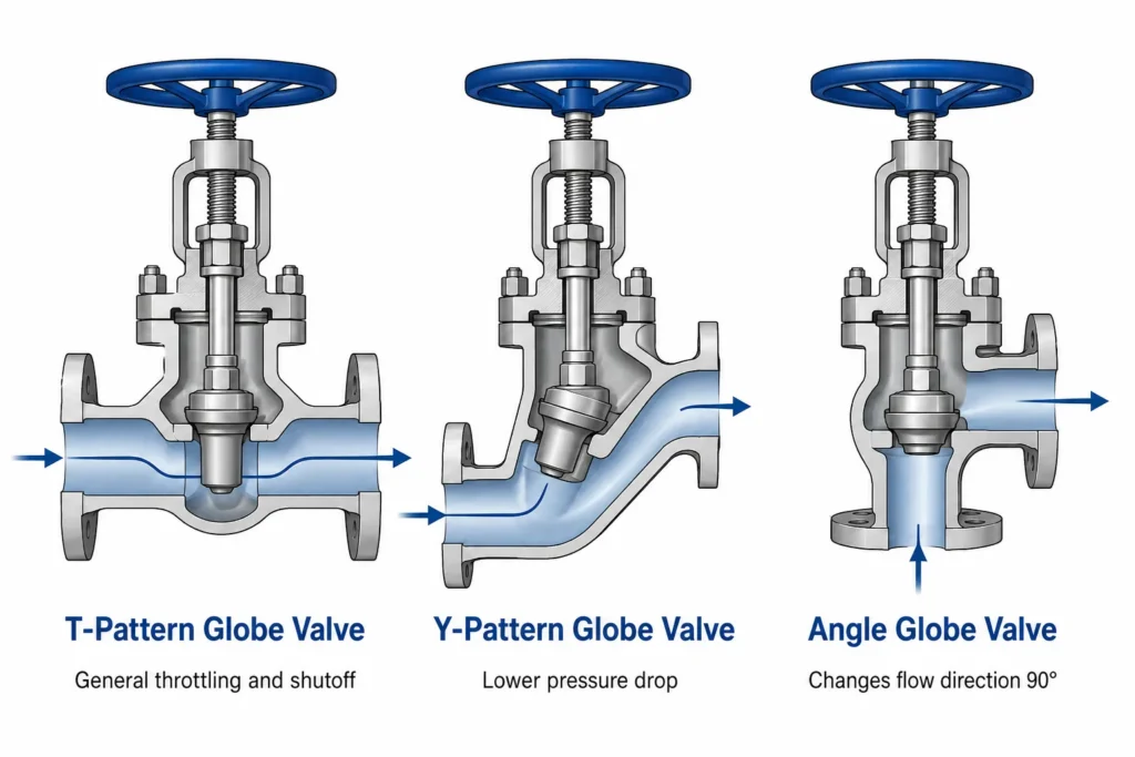
Resumen de los tipos de válvulas de bola
Los tres diseños principales del cuerpo de las válvulas de bola son el diseño en T, el diseño en Y y el diseño angular. Las válvulas de globo también se pueden clasificar en válvulas de vástago empaquetado y de sellado con fuelle, válvulas de tapa atornillada y de sellado a presión, válvulas de asiento blando y de asiento metálico, y válvulas de cierre manual o de control automático.
El tipo adecuado depende de si la prioridad es una regulación precisa, una baja pérdida de presión, la dirección de las tuberías, el servicio de vapor a alta presión, una menor fuga en el vástago o el control automático del proceso.
Válvula de bola tipo T
El diseño convencional de vía recta ofrece un cierre y una regulación confiables, pero genera una caída de presión relativamente alta.
Válvula de bola con diseño en Y
El vástago y el asiento inclinados crean un paso de flujo más suave y reducen la pérdida de presión en comparación con un cuerpo convencional con diseño en T.
Válvula de globo angular
La entrada y la salida están dispuestas en un ángulo de aproximadamente 90 grados, lo que permite que la válvula controle el flujo al tiempo que cambia la dirección de la tubería.
Válvula de globo con sello de fuelle
Un fuelle metálico soldado separa el fluido de proceso del vástago móvil y reduce el riesgo de fugas a través de la zona de empaque.
¿Qué es una válvula de bola?
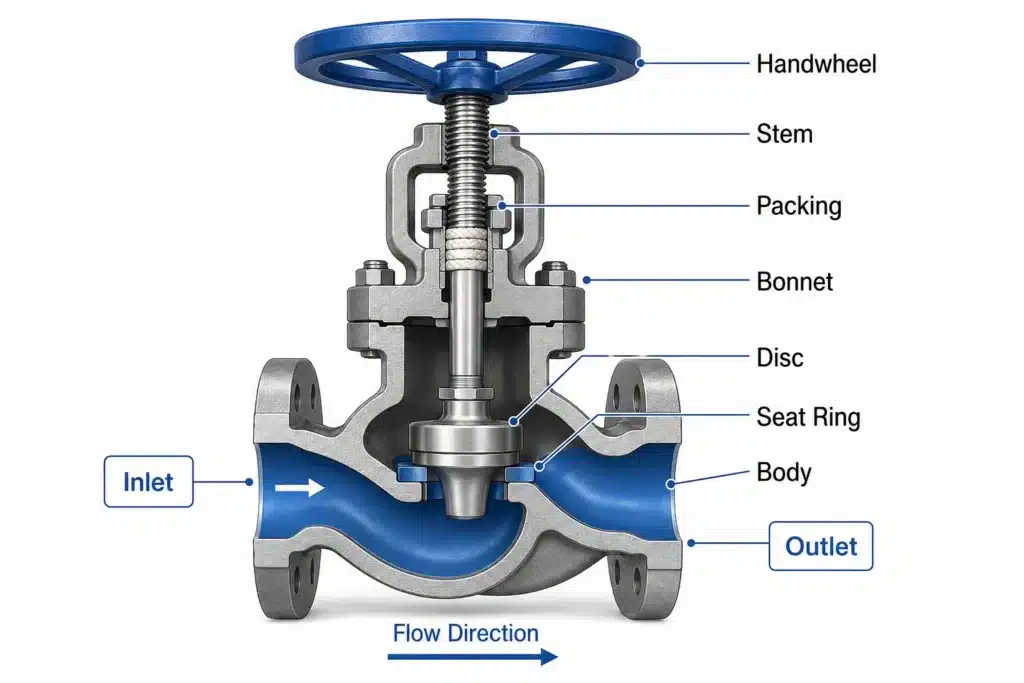
Una válvula de bola consta de un cuerpo de válvula, una tapa, un vástago, un disco o obturador, un anillo de asiento y un sistema de sellado del vástago. Al girar el volante o accionar un actuador, el vástago se eleva o desciende. El movimiento del vástago modifica la distancia entre el disco y el asiento, lo que a su vez modifica el área de flujo disponible.
Cuando el disco está completamente elevado, el fluido pasa a través del cuerpo de la válvula y la abertura del asiento. A medida que el disco se acerca al asiento, la válvula restringe el flujo y genera una mayor caída de presión. Cuando el disco entra en contacto con el asiento, la válvula detiene el flujo.
El paso interno suele ser más restrictivo que el paso recto de una válvula de bola o el paso totalmente abierto de una válvula de compuerta. Esto genera una mayor pérdida de presión, pero es precisamente esa restricción controlada la que permite que una válvula de globo proporcione una regulación estable.
El término “globo” se refería originalmente a la forma redondeada de los primeros cuerpos de válvula. Las válvulas de globo modernas pueden tener cuerpos rectos, angulados, compactos o en forma de Y, aunque siguen utilizando el mismo principio básico de funcionamiento lineal de disco y asiento.
1. Válvula de bola tipo T
La válvula de globo tipo T, también conocida como válvula de globo estándar o convencional, es el diseño de válvula de globo más reconocible. Sus conexiones de entrada y salida se encuentran en la misma línea central, mientras que el asiento está ubicado transversalmente al paso interno.
El fluido que ingresa a la válvula cambia de dirección a medida que avanza hacia la abertura del asiento y vuelve a cambiar de dirección antes de salir del cuerpo. Estos cambios de dirección generan turbulencias y una caída de presión relativamente alta.
El diseño en forma de T se utiliza ampliamente porque ofrece una regulación eficaz, un cierre confiable y una forma práctica del cuerpo para numerosas aplicaciones industriales. Se instala comúnmente en líneas de vapor, condensado, agua de enfriamiento, combustible, derivación y procesos en general.
Una válvula de globo tipo T es una excelente opción cuando la pérdida de presión es aceptable y el ajuste controlado del flujo es más importante que la máxima eficiencia de flujo. El cuerpo convencional también ofrece una disposición estable del asiento y puede adaptarse a varios diseños de disco y componentes internos.
Aplicaciones típicas del patrón en T
Las válvulas de bola tipo T se utilizan comúnmente para el aislamiento de vapor, derivaciones de equipos, control de descarga de bombas, sistemas auxiliares de calderas y líneas de proceso que requieren un funcionamiento frecuente. Se pueden suministrar como válvulas de cierre manuales o como válvulas de control accionadas.
2. Válvula de bola con diseño en Y
Una válvula de globo con diseño en Y coloca el vástago, el disco y el asiento en ángulo con respecto a la tubería principal. El cuerpo y la tapa forman una figura similar a la letra Y.
La disposición inclinada crea un paso de flujo más recto y suave que el de una válvula convencional con diseño en T. El fluido cambia de dirección de manera menos brusca al pasar por el asiento, lo que reduce la turbulencia y la pérdida de presión.
La válvula de globo con diseño en Y suele elegirse para aplicaciones de alta presión o alta temperatura, en las que la válvula permanece completamente abierta durante largos períodos, pero debe seguir proporcionando un aislamiento confiable. La menor pérdida de presión ayuda a reducir la energía de bombeo o compresión cuando es importante mantener un flujo continuo.
Los diseños en forma de Y son comunes en sistemas de vapor, agua de alimentación de calderas, generación de energía y procesos de alta presión. Pueden suministrarse con tapas atornilladas, tapas soldadas o con sellado a presión, dependiendo de la clase de presión y la aplicación.
El vástago en ángulo requiere un espacio suficiente para su instalación y mantenimiento. Por lo tanto, se debe revisar la orientación de la válvula y la disposición del actuador durante el diseño de las tuberías.
Cuándo elegir una válvula en forma de Y
Vale la pena considerar una válvula de globo con diseño en Y cuando el sistema requiere el rendimiento de cierre o regulación de una válvula de globo, pero no puede soportar la pérdida total de presión asociada con un cuerpo convencional con diseño en T.
3. Válvula de globo angular
Una válvula de globo angular tiene conexiones de entrada y salida situadas a aproximadamente 90 grados entre sí. La válvula cambia la dirección de la tubería al tiempo que controla o aísla el flujo.
Dado que el cuerpo cumple la función tanto de válvula como de codo de tubería, una válvula de bola en ángulo puede reducir el número de accesorios independientes en el sistema de tuberías. Esto puede simplificar el trazado en los casos en que la tubería deba girar cerca del punto de control o de aislamiento.
Las válvulas de bola angulares se utilizan en la purga de calderas, en sistemas de vapor, en drenajes, en sistemas de condensado, en estaciones reductoras de presión y en líneas de proceso en las que la dirección del fluido cambia al pasar por la válvula.
En aplicaciones con golpes de ariete o erosión, una válvula de control de cuerpo angular puede dirigir el flujo de salida de alta velocidad hacia una conexión aguas abajo más grande o especialmente protegida. Algunos diseños pueden incluir componentes internos endurecidos, revestimientos de salida o secciones de salida ensanchadas.
Las tuberías de salida deben estar bien apoyadas, ya que el cambio en la dirección del flujo genera fuerzas de reacción. La dirección preferida del flujo y la orientación de la válvula deben seguir las instrucciones de diseño del fabricante.
Comparación de los diseños de los cuerpos de las válvulas de bola
| Patrón corporal | Trayectoria interna del flujo | Caída de presión | Motivo típico de selección |
|---|---|---|---|
| Válvula de globo con diseño en T | El fluido cambia de dirección al pasar por un cuerpo convencional de tramo recto. | Relativamente alto | Regulación general, cierre y funcionamiento frecuente |
| Válvula de bola con diseño en Y | El vástago y el asiento están inclinados para facilitar el paso. | Más bajo que un diseño en forma de T | Funcionamiento a alta presión y menor resistencia al flujo |
| Válvula de globo angular | El fluido entra y sale a través de conexiones dispuestas a 90 grados. | Depende del diseño de la carrocería y del acabado | Control de flujo combinado con un cambio de dirección en la tubería |
4. Válvula de globo de disco convencional
Una válvula de globo de disco convencional utiliza un disco relativamente plano o ligeramente cónico que se desplaza contra el asiento de la válvula. Este diseño permite un funcionamiento sencillo de tipo “abierto-cerrado” y se utiliza comúnmente en servicios públicos generales.
El área de contacto del asiento y el material determinan el rendimiento de cierre. Los asientos de metal contra metal pueden soportar temperaturas más altas, mientras que un elemento de sellado elástico puede proporcionar un cierre más hermético en aplicaciones compatibles a temperaturas más bajas.
Los discos convencionales son adecuados cuando la válvula se utiliza principalmente para el aislamiento, con un ajuste ocasional del flujo. Para un funcionamiento modulado continuo, un obturador perfilado o un conjunto de control diseñado específicamente suelen ofrecer una característica de flujo más predecible.
5. Válvula de bola tipo tapón
Una válvula de globo tipo tapón utiliza un elemento de cierre largo, cónico o perfilado, en lugar de un disco plano. El tapón se introduce en la abertura del asiento a medida que la válvula se cierra.
El perfil del obturador puede diseñarse de tal manera que cada incremento en el recorrido del vástago genere un cambio controlado en el área de paso. Esto hace que las válvulas de globo de tipo obturador sean adecuadas para la regulación del caudal y el control automático de procesos.
Los obturadores de las válvulas de control pueden estar diseñados para ofrecer características de flujo lineales, de porcentaje igual o de apertura rápida. La característica adecuada depende de la distribución de la presión y de la respuesta de todo el sistema de tuberías.
Las superficies del obturador y los anillos de asiento pueden estar endurecidos para su uso con vapor, agua a alta presión o fluidos de proceso erosivos. En el funcionamiento automático, el obturador está conectado a un actuador lineal neumático, eléctrico o hidráulico.
6. Válvula de globo tipo aguja
Una válvula de aguja es un diseño especializado de paso pequeño basado en el principio de la válvula de globo. Utiliza una aguja cónica, larga y estrecha, que se introduce en una pequeña abertura del asiento.
El perfil gradual de la aguja permite ajustes muy precisos en el área de flujo. Por ello, las válvulas de aguja se utilizan en instrumentación, manómetros, sistemas de muestreo, equipos hidráulicos e inyección química de bajo flujo.
Las válvulas de aguja están diseñadas para caudales relativamente pequeños. Normalmente no se utilizan como válvula de control principal en una tubería industrial de gran tamaño.
Al comprar una válvula de aguja, el comprador debe verificar la presión nominal, el diseño de la punta del vástago, el tamaño del orificio, la conexión final y la compatibilidad con el medio de proceso.
7. Válvula de globo con asiento blando
Una válvula de bola con asiento blando utiliza un polímero elástico o un elastómero en la interfaz entre el disco y el asiento. El material de sellado más blando puede adaptarse a pequeñas imperfecciones de la superficie y proporcionar un cierre hermético con una fuerza de cierre moderada.
Las válvulas de asiento blando se utilizan en aplicaciones de agua, aire, climatización (HVAC) y productos químicos compatibles. Entre los materiales de sellado más comunes se encuentran el EPDM, el NBR, el PTFE y otros polímeros de ingeniería.
El material del asiento debe seleccionarse en función del fluido concreto, la concentración, la presión y la temperatura. Un material que funcione bien con agua puede no ser adecuado para aceite, solventes, vapor o gases a altas temperaturas.
El límite de presión y temperatura de la válvula completa puede ser inferior al valor nominal del cuerpo metálico, ya que el asiento blando, la empaquetadura y los sellos del cuerpo pueden determinar las condiciones de servicio permitidas.
8. Válvula de bola con asiento metálico
Una válvula de bola con asiento metálico cuenta con superficies de asiento metálicas en el disco o el obturador y en el anillo de asiento. Los asientos metálicos se eligen para aplicaciones con vapor, altas temperaturas, fluidos abrasivos y condiciones de funcionamiento que superan la capacidad de los materiales elásticos.
Las superficies de los asientos pueden estar fabricadas con acero inoxidable, aleaciones endurecidas o materiales de recubrimiento duro para mejorar la resistencia a la erosión, la corrosión y el funcionamiento repetido.
Las válvulas con asiento metálico requieren un mecanizado y una alineación precisos para lograr un cierre confiable. Se debe especificar claramente su tasa de fuga permitida, ya que el asiento metal contra metal puede evaluarse de manera diferente al asiento elástico.
En condiciones de estrangulamiento severo, el disco y el asiento pueden estar expuestos a alta velocidad, cavitación o erosión por tracción de alambre. Por lo tanto, la dureza y la geometría de los componentes deben seleccionarse en función de la caída de presión real y las condiciones del fluido.
9. Válvula de bola con vástago empaquetado
Una válvula de bola con vástago empaquetado utiliza anillos de empaque comprimidos alrededor del vástago de la válvula para evitar que el fluido de proceso se escape a través del casquillo.
La empaquetadura se comprime mediante una prensaestopas y un empujador. Es importante que la compresión sea la adecuada: una compresión insuficiente puede provocar fugas externas, mientras que una compresión excesiva aumenta la fricción del vástago y la fuerza del actuador.
Entre los materiales de empaque más comunes se encuentran el grafito, el PTFE y combinaciones de materiales de ingeniería seleccionadas en función de la temperatura, la compatibilidad química y los requisitos de emisiones fugitivas.
La construcción con empaque en el vástago se utiliza ampliamente porque el empaque se puede ajustar o reemplazar durante el mantenimiento programado. El servicio de bajas emisiones puede requerir empaque sometido a carga en operación, superficies pulidas del vástago y pruebas de calificación.
10. Válvula de bola con sello de fuelle
Una válvula de globo con sello de fuelle cuenta con un fuelle metálico flexible soldado alrededor del vástago. Un extremo del fuelle está unido al vástago, mientras que el otro está conectado al sombrero o al cuerpo de la válvula.
A medida que se mueve el vástago, el fuelle se expande y se contrae sin permitir que el fluido de proceso llegue al área principal de empaque. Esto crea una barrera de presión adicional y reduce considerablemente la posibilidad de fugas rutinarias en el vástago.
Las válvulas de bola con sello de fuelle se utilizan para fluidos tóxicos, peligrosos, de alta pureza, radiactivos o costosos, en los que es necesario minimizar las fugas externas. Entre sus aplicaciones más comunes se incluyen el procesamiento químico, los sistemas de vacío, los fluidos de transferencia de calor y ciertos servicios nucleares o farmacéuticos.
Muchos diseños conservan una empaquetadura secundaria del vástago por encima del fuelle. La empaquetadura proporciona un sellado adicional en caso de que el fuelle se dañe y también puede evitar que entre contaminación externa al sombrerete.
Se deben evaluar cuidadosamente el material del fuelle, su vida útil, su carrera y su capacidad de resistencia a la presión y la temperatura. No se debe elegir la válvula únicamente porque se describa como sellada con fuelle.
Punto de adquisición de válvulas de fuelle
Solicite en la cotización técnica del proveedor el material del fuelle, el número de capas, la vida útil certificada, la presión de diseño, la temperatura de diseño y la disposición de la empaque secundaria.
11. Válvula de globo con tapa atornillada
Una válvula de globo con casquillo atornillado utiliza una conexión atornillada entre el cuerpo de la válvula y el casquillo. Una junta o sello de presión evita las fugas a través de la unión.
El diseño de la tapa atornillada permite un acceso práctico a los componentes del disco, el asiento y el vástago durante el mantenimiento. Se utiliza ampliamente en válvulas de globo fundidas y forjadas en aplicaciones de baja, media y alta presión.
El sistema de fijación del tapón, el material de la junta y el diseño de la unión deben ser adecuados para la presión y la temperatura. El reensamblaje requiere que las superficies de sellado estén limpias y que se siga una secuencia controlada de apriete de los tornillos.
En aplicaciones a altas temperaturas, los ciclos térmicos pueden afectar la compresión de las juntas y la tensión de los pernos. Se debe seguir el procedimiento de mantenimiento del fabricante de la válvula, en lugar de aplicar un método general de apriete de pernos de brida.
12. Válvula de globo con tapa soldada
Una válvula de bola con tapa soldada une la tapa al cuerpo mediante una unión soldada a presión. Esto elimina la necesidad de una junta convencional en la tapa y puede reducir el número de vías de fuga externas.
La construcción con tapa soldada se utiliza con frecuencia en válvulas compactas de acero forjado para vapor a alta presión, agua y aplicaciones de proceso. Ofrece un ensamblaje resistente y compacto en los casos en que no se prevé un acceso interno habitual.
Los compradores deben saber si la tapa está totalmente soldada, soldada con junta de sellado o si cuenta con otro diseño específico del fabricante. Los procedimientos de mantenimiento y reemplazo pueden diferir significativamente de los de una válvula con tapa atornillada.
13. Válvula de globo con sellado a presión
Una válvula de globo con sellado por presión utiliza la presión interna del sistema para aumentar la fuerza de sellado en la unión entre el cuerpo y la tapa. A medida que aumenta la presión, la junta de sellado por presión se presiona con mayor firmeza contra las superficies de sellado.
Esta construcción se utiliza ampliamente en sistemas de generación de energía a alta presión y alta temperatura, incluyendo el vapor principal, el agua de alimentación de la caldera y los servicios relacionados.
Las válvulas de sellado por presión están disponibles en configuraciones tipo T, tipo Y y en ángulo. Pueden utilizar accionamientos manuales, cajas de engranajes o actuadores eléctricos, neumáticos e hidráulicos.
Es fundamental instalar correctamente la junta de sellado a presión, el anillo espaciador, los componentes de retención y la tapa. El mantenimiento debe ser realizado por personal que esté familiarizado con el diseño específico de la válvula.
14. Válvula de control de globo de un solo asiento
Una válvula de control de globo de un solo asiento cuenta con un obturador y un anillo de asiento. Su diseño permite un cierre confiable y un paso de flujo bien definido.
Dado que la presión del proceso actúa sobre toda el área del obturador, el actuador debe generar suficiente empuje para mover y asentar el obturador bajo la presión diferencial máxima. La fuerza requerida del actuador puede llegar a ser significativa a medida que aumentan el tamaño de la válvula y la caída de presión.
Las válvulas de un solo asiento se utilizan ampliamente para el control de procesos de vapor, gas, líquidos y productos químicos. Pueden suministrarse con obturadores no equilibrados para un cierre sencillo o con obturadores equilibrados a presión para reducir el empuje del actuador.
15. Válvula de control de globo de doble asiento
Una válvula de control tipo globo de doble asiento utiliza dos obturadores y dos anillos de asiento dispuestos de tal manera que las fuerzas del proceso se oponen parcialmente entre sí. Esto puede reducir el empuje neto que debe ejercer el actuador.
Este diseño se ha utilizado tradicionalmente en aplicaciones en las que es importante contar con una gran capacidad de flujo y una menor fuerza de accionamiento. Lograr un contacto hermético simultáneo en ambos asientos puede resultar más difícil que con una válvula de un solo asiento, por lo que se debe tomar en cuenta la clase de cierre requerida al momento de la selección.
Las válvulas de control modernas, de un solo asiento y guiadas por jaula, también se utilizan ampliamente para gestionar la fuerza del actuador y, al mismo tiempo, proporcionar un rendimiento de ajuste predecible.
16. Válvula de control de globo con guía de jaula
Una válvula de bola guiada por jaula utiliza una jaula cilíndrica o un retenedor que rodea el obturador. La jaula guía el movimiento del obturador, sujeta el anillo de asiento y puede incluir aberturas de flujo con formas especiales.
Al modificar el tamaño y la forma de las aberturas de la jaula, los fabricantes pueden generar diferentes características de flujo y controlar el ruido, la cavitación o las altas caídas de presión.
Las válvulas de control con guía de jaula se utilizan en plantas de proceso, centrales eléctricas, instalaciones de petróleo y gas y sistemas de vapor que requieren una regulación automática.
El conjunto interno puede diseñarse para control estándar, bajo nivel de ruido, anticavitación, reducción de presión multietapa o servicio con fluidos sucios. El diseño adecuado debe seleccionarse basándose en el dimensionamiento de la válvula de control y no únicamente en el tamaño de la tubería.
17. Válvulas de bola equilibradas y desequilibradas
El obturador de una válvula de bola desequilibrada está expuesto a la diferencia de presión del proceso a lo largo de una superficie considerable del obturador. El actuador debe superar esta fuerza de presión, así como la fricción de la empaquetadura y la fuerza de asiento.
Un obturador equilibrado cuenta con conductos internos y elementos de sellado que reducen la fuerza de presión efectiva que actúa sobre el obturador. Esto permite que un actuador más pequeño controle una válvula más grande o una presión diferencial más alta.
Una construcción equilibrada puede incluir anillos de pistón, sellos o sistemas de guía. Los componentes de sellado deben ser compatibles con la temperatura del proceso y el fluido.
Al comparar cotizaciones de válvulas de control, los compradores deben confirmar si el conjunto interno es equilibrado o desequilibrado y revisar el empuje calculado del actuador a la presión diferencial máxima.
18. Válvula de bola de cierre
Una válvula de bola de cierre está diseñada principalmente para aislar la tubería, aunque su diseño de disco y asiento también puede permitir el control manual del flujo. Por lo general, se acciona mediante un volante o una caja de engranajes.
Las válvulas de cierre se utilizan en sistemas de vapor, agua, aceite y servicios públicos en general. El disco puede ser convencional, cónico o en forma de tapón, según los requisitos de cierre y regulación.
El operador debe evitar aplicar una fuerza excesiva al volante una vez que el disco entre en contacto con el asiento. Una fuerza excesiva puede dañar el vástago, el disco, el asiento o las roscas de accionamiento.
19. Válvula de control Globe
Una válvula de control tipo globo está diseñada para regular automáticamente el flujo del proceso. Combina un cuerpo tipo globo y un conjunto de control con un actuador neumático, eléctrico o hidráulico.
Un sensor mide el flujo, la presión, la temperatura o el nivel, y un controlador envía una señal al actuador. El actuador modifica la posición del obturador hasta que el proceso medido se aproxima al punto de ajuste requerido.
Las válvulas de control se dimensionan de acuerdo con la capacidad de flujo, la caída de presión, las propiedades del fluido y el rango de control requerido. Seleccionar una válvula de control basándose únicamente en el diámetro de la tubería puede dar lugar a una válvula sobredimensionada con un funcionamiento inestable a baja carrera.
Al seleccionar una válvula de control, también se deben evaluar la cavitación, la vaporización, el flujo estrangulado, el ruido aerodinámico, la posición de fallo del actuador y el rendimiento de cierre requerido.
20. Válvula de bola con cierre y control
Una válvula de globo con retén de cierre combina las funciones de una válvula de aislamiento de globo y una válvula de retención de elevación. Se puede cerrar manualmente para aislar la tubería, mientras que su disco se mueve automáticamente para evitar el flujo inverso cuando la válvula se coloca en la posición de funcionamiento.
Las válvulas de retención se utilizan en sistemas de calderas, vapor y generación de energía, donde los operadores necesitan tanto aislamiento manual como protección contra el reflujo.
El diseño interno y el procedimiento de operación difieren de los de una válvula de globo convencional. Los compradores deben verificar la dirección del flujo, el guiado del disco, la interacción manual del vástago y el funcionamiento de la válvula de retención.
Válvulas de globo manuales, eléctricas y neumáticas
Válvula de bola manual
Una válvula de bola manual se acciona mediante un volante, un volante de impacto o una caja de engranajes. El accionamiento manual es adecuado cuando el movimiento de la válvula es poco frecuente y la instalación es accesible para los operadores.
El volante hace girar el mecanismo del vástago roscado y convierte el movimiento giratorio en un desplazamiento lineal del disco. Un indicador de posición puede mostrar si la válvula está abierta, cerrada o parcialmente abierta.
Válvula de bola de accionamiento eléctrico
Una válvula de bola eléctrica utiliza un actuador eléctrico multigiro o lineal. Es adecuada para el aislamiento y el control a distancia en lugares donde haya suministro eléctrico.
Los actuadores eléctricos pueden incluir controles locales, control manual de emergencia, indicación de posición, protección contra par excesivo y comunicación digital. El actuador debe dimensionarse según el empuje del vástago, el tiempo de operación y el ciclo de trabajo requerido.
Válvula de globo neumática
Una válvula de bola neumática suele utilizar un actuador de diafragma o de pistón. El accionamiento neumático ofrece una respuesta rápida y se utiliza ampliamente para el control automático de procesos.
Los actuadores con retorno por resorte pueden mover la válvula a una posición de “fallo abierto” o “fallo cerrado” en caso de que se pierda el aire de instrumentación. Un posicionador proporciona un posicionamiento intermedio preciso para el servicio de modulación.
Materiales de las válvulas de bola
Los materiales del cuerpo de las válvulas de bola se seleccionan de acuerdo con la presión, la temperatura, las características químicas del proceso y el entorno externo.
Las válvulas de hierro fundido y de hierro dúctil se utilizan ampliamente en sistemas de agua, climatización y servicios públicos de presión moderada. El acero al carbono proporciona la resistencia mecánica necesaria para sistemas de petróleo, gas, vapor y procesos industriales en general.
El acero inoxidable se elige para numerosas aplicaciones corrosivas, sanitarias y con fluidos limpios. Los aceros aleados se utilizan para vapor a altas temperaturas y para la generación de energía. El acero inoxidable dúplex y las aleaciones especiales pueden ser necesarios para aplicaciones que contengan cloruro o para servicios químicos severos.
El material del cuerpo por sí solo no determina la compatibilidad. Los materiales del disco, el asiento, el vástago, el empaque, la junta y el actuador también deben ser adecuados para las condiciones del proceso.
Cómo elegir el tipo correcto de válvula de bola
La selección de una válvula de globo debe partir de la función requerida. Una válvula de aislamiento de accionamiento manual, una válvula de regulación de vapor y una válvula automática de control de presión pueden utilizar cuerpos tipo globo, pero sus requisitos en cuanto a componentes internos y actuadores son diferentes.
- Defina la función de la válvula. Determine si la válvula servirá para aislar, estrangular, regular automáticamente o impedir el flujo inverso.
- Identifique el fluido de proceso. Verifique la composición química, el contenido de sólidos, la toxicidad, la corrosividad y los requisitos de contaminación.
- Confirma la presión y la temperatura. Incluye las condiciones normales, máximas, de arranque, de apagado y de limpieza.
- Selecciona el patrón del cuerpo. Elige entre la construcción con patrón en T, en Y o angular, según la caída de presión y el trazado de las tuberías.
- Seleccione el tipo de válvula. Elija el disco, el tapón, el asiento, la jaula y el sistema de equilibrado de acuerdo con los requisitos de cierre y control.
- Selecciona el sello del vástago. Elige entre empaque convencional, empaque de baja emisión o sello de fuelle, según el riesgo de fugas.
- Selecciona la tapa. Evalúa si la construcción debe ser atornillada, soldada o con sellado a presión, de acuerdo con la presión, la temperatura y el mantenimiento.
- Seleccione el operador. Elija un volante, una caja de engranajes, un actuador eléctrico o un actuador neumático según las condiciones de acceso y las exigencias de control.
Lista de verificación para la adquisición de válvulas de bola
Información que debe incluirse en la solicitud de cotización
- Tipo de válvula de bola y función requerida
- Tamaño nominal de tuberías y válvulas
- Clase de presión o designación de presión
- Cuerpo con diseño en T, en Y o en ángulo
- Medio de proceso y concentración
- Temperatura mínima, normal y máxima
- Presión diferencial normal y máxima
- Caudal requerido o Cv/Kv de la válvula de control
- Materiales del cuerpo, la tapa, el vástago, el disco y el asiento
- Diseño con asiento blando o con asiento metálico
- Sello de vástago empaquetado o de fuelle
- Tapa atornillada, soldada o con sellado a presión
- Extremos con brida, roscados, para soldadura por encaje o para soldadura a tope
- Norma de referencia para la fuga de los asientos y las pruebas correspondientes
- Operación manual, eléctrica o neumática
- Acción de apertura en caso de falla, cierre en caso de falla o permanencia en su posición en caso de falla
- Requisitos de seguridad contra incendios o de emisiones fugitivas
- Certificados de materiales e informes de inspección
- Repuestos y kits de mantenimiento recomendados
Aplicaciones de las válvulas de bola
Las válvulas de bola se utilizan ampliamente en el suministro y la distribución de vapor, ya que permiten una apertura gradual, un cierre eficaz y un ajuste controlado del flujo. Las válvulas tipo Y y las de sellado por presión son comunes en aplicaciones de energía a alta presión, mientras que las válvulas convencionales tipo T se utilizan en líneas generales de vapor y de servicios públicos.
En los sistemas de agua de enfriamiento y de climatización (HVAC), las válvulas de globo con asiento blando regulan el flujo en los intercambiadores de calor y los serpentines. Las válvulas de control automáticas de tipo globo responden a las señales de temperatura o presión que provienen del sistema de control de la planta.
Las plantas químicas utilizan válvulas de globo de acero inoxidable, de aleación y con sellado de fuelle para fluidos corrosivos, tóxicos o de alta pureza. La compatibilidad de los materiales y los requisitos de fugas externas son particularmente importantes en estas aplicaciones.
Las instalaciones de petróleo y gas utilizan válvulas de bola para la regulación del combustible, las líneas de derivación, los sistemas de compresión y el control de procesos. Es posible que se requiera un conjunto interno endurecido cuando la reducción de presión provoque erosión o altas velocidades.
Los sistemas de calderas y generación de energía utilizan válvulas de bola de cierre, de cierre con control, de patrón en Y y de sellado por presión en los circuitos de vapor, agua de alimentación, drenajes y ventilaciones.
Consideraciones para la instalación de válvulas de bola
Las válvulas de bola pueden ser direccionales. La presión del proceso que actúa por debajo o por encima del disco afecta la fuerza de operación, el cierre y la estabilidad de la válvula. La válvula debe instalarse de acuerdo con la flecha de flujo y las instrucciones del fabricante.
Las tuberías deben estar limpias antes de la instalación, ya que las escorias de soldadura, el óxido y los residuos pueden dañar el disco y el asiento. Los soportes de las tuberías deben evitar que actúen cargas excesivas sobre el cuerpo de la válvula.
Las válvulas con bridas requieren bridas de acoplamiento limpias y alineadas, así como juntas compatibles. Las válvulas con extremos para soldar deben protegerse del calor excesivo y de la contaminación por soldadura.
Las válvulas manuales necesitan espacio suficiente para el manejo del volante y el recorrido del vástago. Las válvulas accionadas requieren espacio libre para el actuador, el acceso para el mantenimiento y la extracción de la tapa o el conjunto interno.
Seguridad en el mantenimiento
Nunca aflojes los pernos de la tapa, los componentes de empaque, los tapones de drenaje ni las conexiones del actuador mientras la válvula esté presurizada. La tubería debe aislarse, despresurizarse, drenarse y verificarse que sea segura antes de abrir la compuerta de presión.
Preguntas frecuentes sobre los tipos de válvulas de bola
¿Cuáles son los tres tipos principales de cuerpos de válvulas de bola?
Los tres tipos principales de cuerpo son la válvula de globo tipo T, la válvula de globo tipo Y y la válvula de globo angular.
¿Qué válvula de bola tiene la menor caída de presión?
Una válvula de globo con diseño en Y suele ofrecer un recorrido de flujo más suave y una caída de presión menor que una válvula de globo convencional con diseño en T.
¿Qué es una válvula de globo angular?
Una válvula de bola angular tiene las conexiones de entrada y salida dispuestas a aproximadamente 90 grados. Controla el flujo al tiempo que cambia la dirección de la tubería.
¿Qué es una válvula de globo con sello de fuelle?
Una válvula de globo con sello de fuelle utiliza un fuelle metálico flexible soldado alrededor del vástago para separar el fluido de proceso del área principal de empaque y reducir las fugas externas.
¿Qué es una válvula de globo con sellado a presión?
Una válvula de globo con sellado por presión utiliza la presión interna del proceso para aumentar la fuerza de sellado en la unión entre el cuerpo y la tapa. Se utiliza comúnmente en aplicaciones de alta presión y alta temperatura.
¿Cuál es la válvula de bola más adecuada para el vapor?
El tipo más adecuado depende de la presión del vapor, la temperatura y la función requerida. Las válvulas de tipo T se utilizan para aplicaciones generales de vapor, mientras que las de tipo Y y las de sellado a presión suelen elegirse para sistemas de mayor presión.
¿Cuál es la diferencia entre las válvulas de globo con asiento blando y las de asiento metálico?
Los asientos blandos pueden proporcionar un cierre hermético en aplicaciones compatibles a temperaturas moderadas. Los asientos metálicos se eligen para temperaturas más altas, vapor, abrasión y condiciones operativas severas.
¿Qué es una válvula de bola guiada por jaula?
Una válvula guiada por jaula utiliza una jaula cilíndrica para guiar el obturador, retener los componentes internos y generar la característica de flujo o el comportamiento de reducción de presión requeridos.
¿Las válvulas de bola pueden accionarse eléctricamente?
Sí. Los actuadores eléctricos pueden accionar válvulas de bola para el aislamiento remoto o el control modulado. El actuador debe estar dimensionado para el empuje del vástago y el ciclo de trabajo requeridos.
¿Cómo elijo un tipo de válvula de bola?
Antes de realizar la selección, confirme la función requerida, el fluido, la presión, la temperatura, el caudal, la caída de presión admisible, la compatibilidad de materiales, los requisitos de fugas, el método de sellado del vástago y el tipo de accionamiento.
Conclusión
Existen muchos tipos de válvulas de bola, y cada diseño responde a una combinación diferente de control de flujo, cierre, caída de presión, fugas en el vástago, presión nominal y requisitos de mantenimiento.
Las válvulas de globo tipo T sirven para la regulación general y el aislamiento; las válvulas tipo Y reducen la resistencia al flujo, y las válvulas de globo angulares combinan el control con un cambio en la dirección de la tubería. Las válvulas con sellado de fuelle reducen las fugas en el vástago, mientras que las válvulas con sellado a presión se utilizan en sistemas exigentes de alta presión y alta temperatura.
El diseño del disco, el material del asiento, la construcción del sombrero y la selección del actuador son tan importantes como la forma externa del cuerpo. Una válvula de bola confiable debe seleccionarse en función de todas las condiciones del proceso, y no solo en función del tamaño de la tubería o la clase de presión.
Proporcionar datos técnicos completos en la solicitud de compra ayuda al proveedor a recomendar una válvula de bola que ofrezca un control estable, un cierre confiable y un mantenimiento práctico a largo plazo.