


What is Electric Control Valve?
An electric control valve is an automated valve that uses an electric actuator to position the valve opening according to a control signal. By changing the flow area inside the valve, it can regulate liquid, gas or steam flow and help maintain process variables such as pressure, temperature, flow rate or tank level.
Unlike a simple electrically operated on-off valve, an electric control valve is normally designed to move to intermediate positions. A controller may command the valve to 20%, 45%, 70% or another position depending on the difference between the actual process condition and the required setpoint.
Electric control valves are increasingly used in water treatment, HVAC, energy systems, industrial utilities, chemical processing, food production and remote pumping stations. They are particularly attractive where electrical power is readily available but a plant-wide compressed-air system is not.
This guide explains the electric control valve working principle, common valve types, electric actuator functions, control signals, sizing, applications, installation, procurement requirements and the main information engineers should review before selecting an electric actuated control valve.
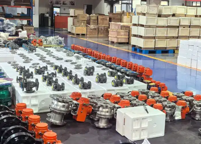
Electric Control Valve Definition
An electric control valve combines a flow-control valve body with a modulating electric actuator. The actuator converts an electrical control command into mechanical movement, while internal position feedback confirms the actual valve position.
The complete assembly may include a ball valve, butterfly valve or globe valve together with an electric actuator, position controller, limit switches, torque protection, position transmitter and manual override.
How Does an Electric Control Valve Work?
The basic operating principle begins with a process measurement. A sensor monitors a variable such as water flow, pipeline pressure, room temperature, tank level or steam temperature and sends the measured value to a controller.
The controller compares the measurement with the required setpoint. If the process variable is too high or too low, it sends a command to the electric control valve. Common analog commands include 4-20 mA and 0-10 V signals, while some industrial systems use digital communication.
The electric actuator receives this signal and energizes its motor. A reduction gearbox converts the motor’s relatively high speed into slower, higher-torque movement suitable for operating the valve.
In a quarter-turn electric control valve, the actuator rotates the valve shaft and moves a ball or butterfly disc. In a linear electric globe valve, the actuator moves the valve stem and plug upward or downward.
A position sensor inside the actuator continuously measures the actual valve position. The actuator compares this feedback with the requested control signal and stops when the required position is reached.
The process controller continues monitoring the system and adjusts the valve whenever operating conditions change. This creates a closed control loop that can maintain a relatively stable flow, pressure, temperature or level.
Main Components of an Electric Control Valve
The performance of an electric control valve depends on both the valve and actuator. Treating the actuator as a simple accessory can lead to poor sizing or control performance.
| المكون | الوظيفة | اعتبارات الاختيار |
|---|---|---|
| جسم الصمام | Contains the process fluid and provides the main flow passage. | Body type and material must suit pressure, temperature and media. |
| Closure element | Ball, disc or plug changes the available flow area. | Geometry affects control characteristic and shutoff capability. |
| Electric motor | Provides the primary driving force. | Voltage, duty cycle and thermal capacity must match service. |
| Gearbox | Reduces motor speed and increases output torque or thrust. | Gear design affects speed, backlash and service life. |
| Position sensor | Measures actual valve position. | Required for accurate modulating operation. |
| Control module | Interprets input signals and controls actuator movement. | Must match the plant signal and communication requirements. |
| Torque or thrust protection | Stops the motor if mechanical load becomes excessive. | Protects the valve and actuator from obstruction or overloading. |
| Manual override | Allows local valve operation when electrical power is unavailable. | Commonly provided as a handwheel. |
| Position feedback | Sends actual valve position to the control system. | May use analog or digital signals. |

Electric Control Valve vs Electric On-Off Valve
An electric on-off valve and an electric control valve may use similar valve bodies and actuators, but they perform different functions.
An on-off valve normally receives only open or close commands. Once energized, the actuator moves until it reaches the fully open or fully closed travel limit. Applications include tank isolation, pipeline switching and equipment sequencing.
A modulating electric control valve can stop at intermediate positions. It receives a proportional command from a process controller and continuously adjusts the valve opening as conditions change.
This difference affects actuator electronics, duty cycle, position sensing and valve sizing. A valve that operates twice per day as an isolation valve has a very different actuator requirement from a control valve that makes small position corrections every few seconds.
Important Selection Point
When requesting an electric control valve quotation, clearly state that the application requires modulating control. The words “electric actuator” alone do not tell the supplier whether the valve will be on-off or continuously modulating.
Common Types of Electric Control Valves
Electric Ball Control Valve
Uses a motorized ball valve for compact control, reliable shutoff and relatively high flow capacity.
Electric Butterfly Control Valve
Provides economical flow regulation in medium- and large-diameter water, HVAC and utility systems.
Electric Globe Control Valve
Uses a linear plug-and-seat design for stable flow, steam and pressure regulation.
Electric V-Port Ball Valve
Uses a characterized ball opening to provide a more predictable relationship between valve position and flow.
Electric Ball Control Valve
An electric ball control valve combines a quarter-turn electric actuator with a ball valve. Standard ball valves contain a circular bore through the ball, while control versions may use a V-port or characterized opening.
V-port ball valves are particularly useful for modulating service because the shaped opening creates a more gradual change in flow area as the ball rotates. This gives the control system more usable travel than a conventional full-port ball valve used only for isolation.
Electric ball control valves are commonly used for water, chemicals, heating and cooling fluids, compressed air and selected process liquids. They provide compact installation and strong shutoff performance.
Valve sizing is important because an oversized ball control valve may provide the normal flow at a very small opening. This reduces usable actuator travel and can make the control loop difficult to stabilize.
Electric Butterfly Control Valve
An electric butterfly control valve uses an electric quarter-turn actuator to rotate a circular disc inside the pipeline. Changing the disc angle changes the available flow area.
Butterfly valves are attractive in large pipe sizes because they are compact, relatively lightweight and economical compared with many large globe valves. They are widely used for cooling water, HVAC, water treatment, ventilation and industrial utility systems.
For control service, the actuator should provide accurate intermediate positioning and enough torque to overcome seat friction and fluid dynamic torque. The valve should also be sized so that normal operation does not occur continually near the fully closed position.
High-performance double-offset butterfly valves may be selected for higher pressure and temperature applications. The disc, seat and actuator must be evaluated as a complete control assembly.
Electric Globe Control Valve
An electric globe control valve uses a linear electric actuator to move a plug toward or away from a stationary seat. The plug profile and seat opening determine how flow capacity changes with stem travel.
Globe valves are commonly selected where stable throttling, high differential pressure or precise process control is more important than minimum pressure loss.
Electric globe valves can regulate hot water, chilled water, thermal oil, steam and process fluids. Different trims can provide linear, equal-percentage or other flow characteristics.
Unlike a quarter-turn actuator rated mainly by torque, a linear globe valve actuator must produce sufficient thrust. Process differential pressure, packing friction and required shutoff force all contribute to the actuator sizing requirement.
What Control Signals Do Electric Control Valves Use?
The control signal tells the actuator what valve position is required. The correct signal must match the plant PLC, DCS, building management system or standalone controller.
4-20 mA Control
A 4-20 mA electric control valve receives an analog current signal. In a typical configuration, 4 mA represents one end of the calibrated travel and 20 mA represents the opposite end.
Intermediate current values correspond to intermediate valve positions. For example, the control system may command a partial opening when process demand is between minimum and maximum.
Current signals are widely used in industrial control because they can travel over relatively long cable distances and make certain wiring faults easier to detect than a simple voltage signal.
0-10 V Control
A 0-10 V signal is common in HVAC, building automation and compact process-control applications. The actuator positions the valve according to the supplied voltage.
Buyers should confirm whether the actuator requires 0-10 V, 2-10 V or another range, because the controller and actuator must use the same calibration.
Digital Communication
Intelligent electric actuators may communicate digitally with the plant control system. Depending on the selected actuator, digital communication can transmit valve position, torque, alarms, operating history and diagnostic information.
Digital communication should be specified only when it matches the site’s control architecture. The protocol, configuration tools and integration responsibility should be defined before purchase.
Electric Control Valve Flow Characteristics
The relationship between actuator travel and fluid flow is called the valve flow characteristic. A valve position of 50% does not necessarily mean that the pipeline flow is 50% of maximum.
A linear characteristic is designed so that equal changes in valve travel produce approximately equal changes in inherent flow capacity. This can be useful where system pressure conditions remain relatively stable.
An equal-percentage characteristic provides smaller capacity changes at low travel and progressively larger changes as the valve opens. This is widely used in process systems where the pressure available across the control valve changes with flow.
The actual installed characteristic also depends on pump curves, pipe resistance, heat exchangers and other system losses. Valve selection should therefore consider the complete system rather than only the inherent valve characteristic.
How to Size an Electric Control Valve
Correct sizing is essential for stable electric control valve performance. Selecting a valve only because its nominal size matches the pipeline can produce an oversized valve.
Control valve sizing begins with minimum, normal and maximum flow requirements together with upstream pressure, downstream pressure and process temperature.
Liquid sizing also considers density, viscosity and vapor pressure, particularly where high pressure drop could create cavitation or flashing. Gas and steam sizing must account for compressibility, pressure ratio and possible choked flow.
From these conditions, the required Cv or Kv is calculated. The selected valve should provide the required normal flow at a useful intermediate position while retaining travel for both increased and reduced demand.
Avoid Oversizing
An oversized electric control valve may operate very close to its closed position during normal service. Small actuator movements can then create large flow changes, leading to unstable control, frequent motor operation and accelerated seat wear.
How to Size the Electric Actuator
The electric actuator must have enough mechanical output to move the valve under the most demanding expected process condition.
Quarter-turn ball and butterfly valves are generally sized according to torque. The calculation may include breakaway torque, running torque, seat friction and fluid dynamic torque.
Linear globe valves require thrust rather than only rotary torque. The actuator must overcome process forces acting on the plug, packing friction and required seating force.
The actuator should be selected from actual valve torque or thrust data supplied by the valve manufacturer. Estimating actuator size only from nominal pipe size is not sufficient.
Buyers should request a sizing calculation showing the valve requirement, actuator output and applied design margin.
Electric Actuator Duty Cycle
Duty cycle describes how frequently the actuator can operate without overheating or exceeding its design limits.
An isolation valve that opens once at the beginning of a production shift and closes once at the end has a relatively light duty. A modulating electric control valve may make hundreds or thousands of small movements during the same period.
Continuous control therefore requires an actuator designed for modulating service. The motor, gearbox, electronics and position-sensing system must tolerate frequent starts and reversals.
Procurement specifications should state the expected control duty and approximate number of movements rather than simply requesting an electric actuator.
Operating Speed and Control Quality
Electric actuator operating speed affects how quickly the process responds. A fast actuator may be desirable for small temperature-control loops, while a slower actuator can be beneficial in large water systems where rapid valve movement could cause pressure surges.
Faster is not always better. If the valve responds much faster than the process itself, the controller may repeatedly overcorrect and cause the valve to hunt around the required position.
The selected actuator speed should therefore match the process dynamics. Some intelligent electric actuators allow different speeds or programmable movement profiles.
Electric Control Valve Fail-Safe Options
Engineers must decide what the valve should do if electrical power or control communication is lost.
A fail-in-place valve stops near its last commanded position. This can be suitable where sudden movement would create an unwanted process upset.
Some electric actuators can move to a fail-open or fail-closed position using a mechanical spring, battery, capacitor or another stored-energy device.
The required fail action should come from the process safety analysis. The specification should also define the required fail speed because a very rapid fail-closed action can create pressure surges in liquid systems.
Manual Override and Local Control
Most industrial electric actuators provide a manual handwheel or another override mechanism. This allows maintenance personnel to move the valve if normal electrical power is unavailable.
Local open, stop and close controls may also be provided on the actuator enclosure. A local-remote selector determines whether commands come from field personnel or the central control system.
For modulating valves, a local position indication helps technicians compare actuator movement with the command signal during commissioning and troubleshooting.
Electric Control Valve Applications
Water Treatment
Electric control valves regulate raw water, filtered water, chemical dosing, tank filling and distribution flow. Electric actuation is especially useful at remote treatment facilities where electrical power is already available but instrument air is not.
HVAC Systems
Electric ball, butterfly and globe valves are widely used in chilled-water, hot-water and condenser-water circuits. A building automation system adjusts the valve according to room temperature, differential pressure or cooling demand.
Pump and Booster Systems
Electric control valves can coordinate with pumps to regulate discharge pressure or system flow. Controlled valve movement can also help reduce sudden hydraulic changes during pump startup and shutdown.
Industrial Heating Systems
Electric globe valves regulate hot water, thermal oil and selected steam applications. The control system adjusts energy flow according to process temperature.
المعالجة الكيميائية
Stainless steel, lined and corrosion-resistant electric control valves are used for chemical flow when the valve materials and actuator enclosure are compatible with the process and environment.
Food and Beverage Processing
Electric control valves regulate water, cleaning fluids and compatible product streams. Sanitary body construction and appropriate sealing materials may be required.
Electric Control Valve vs Pneumatic Control Valve
Both electric and pneumatic control valves can regulate industrial processes, but they use different energy sources and supporting equipment.
An electric control valve requires electrical power and signal wiring. It can be convenient for remote locations and facilities without compressed air. Many electric actuators also integrate local controls, diagnostics and position feedback inside one enclosure.
A pneumatic control valve uses compressed air and normally includes a pneumatic actuator and positioner. Pneumatic systems are common in large process plants where instrument air is already available and frequent fast movement is required.
| مقارنة | صمام التحكم الكهربائي | صمام التحكم الهوائي |
|---|---|---|
| Energy source | Electrical power | Compressed instrument air |
| Control signal | Analog or digital electrical signal | Electrical signal to positioner, converted to air pressure |
| Remote locations | Practical where power is available | Requires an air supply or local compressor |
| Local controls | Often integrated in the actuator | Normally provided through separate accessories |
| Fail action | Stored energy or fail-in-place depending on design | Spring-return fail action is widely available |
| Typical applications | Water, HVAC, utilities and remote systems | Process plants, chemical plants and frequent-cycle control |
How to Select an Electric Control Valve
Selection should begin with the process rather than the actuator catalog. The valve type, flow capacity and material compatibility must first match the system.
- Define the control function. Determine whether the valve regulates flow, pressure, temperature or level.
- Provide process conditions. Record minimum, normal and maximum flow, pressure and temperature.
- Choose the valve type. Select ball, butterfly or globe construction according to pipe size, control accuracy and pressure drop.
- Calculate Cv or Kv. Size the valve from actual process conditions rather than pipe diameter alone.
- Select materials. Confirm body, trim, seat, stem and sealing compatibility.
- Calculate actuator torque or thrust. Use valve manufacturer data at the maximum process differential pressure.
- Define the electrical requirements. State voltage, phase, frequency, control signal and position feedback.
- Confirm control duty. Specify modulating frequency, operating speed and required fail action.
What Buyers Should Check Before Ordering
A technically complete quotation should identify both the valve and actuator. General descriptions such as “DN100 electric control valve” are not enough to compare suppliers.
The valve datasheet should identify the body type, pressure rating, body material, trim, seat material, end connection, flow coefficient and required shutoff performance.
The actuator datasheet should identify power supply, motor rating, torque or thrust, operating speed, modulating duty, enclosure rating, control input and output signals.
The supplier should also state whether the valve and actuator are assembled, calibrated and functionally tested before shipment.
Procurement Recommendation
Purchase the valve, actuator, mounting components and control electronics as one tested package whenever possible. This provides clearer responsibility for actuator sizing, mechanical compatibility, calibration and warranty.
Electric Control Valve RFQ Checklist
- Valve type and required control function
- الحجم الاسمي للصمام والأنبوب
- Pressure class or pressure rating
- Process medium and concentration
- Minimum, normal and maximum flow
- Upstream and downstream pressure
- Minimum and maximum temperature
- Required Cv or Kv
- Body, trim and seat materials
- Required shutoff leakage performance
- Electric actuator torque or thrust
- Power supply voltage, phase and frequency
- 4-20 mA, 0-10 V or digital control signal
- Position feedback requirement
- أوقات الفتح والإغلاق المطلوبة
- Modulating duty and expected cycle frequency
- Fail-open, fail-closed or fail-in-place requirement
- Manual override and local controls
- Ingress protection and ambient temperature
- Hazardous-area requirements where applicable
- Factory calibration and functional testing
- Drawings, wiring diagrams and certificates
- Recommended spare parts
Electric Control Valve Installation
Before installation, verify that the valve flow direction, pipe size, pressure rating and materials match the approved specification. Flush the pipeline to remove welding slag, rust and other debris that could damage the seat or trim.
The piping should be aligned independently. Do not use flange bolts to pull misaligned piping toward the valve because body distortion can affect the sealing surfaces.
The electric actuator should have adequate space for local operation, manual override and maintenance. Cable entries should be sealed correctly to maintain the specified enclosure protection.
Verify the electrical supply before energizing the actuator. Incorrect voltage can damage the motor or control electronics.
After wiring is complete, confirm the command direction. An increasing control signal should move the valve in the direction required by the control strategy.
Commissioning a Modulating Electric Control Valve
Commissioning should verify more than fully open and fully closed operation. A modulating valve should be tested at several intermediate positions.
Apply representative control commands such as 25%, 50% and 75% and verify that actual valve position matches the requested value. Check the position feedback signal at the same time.
Confirm the open and closed travel limits, actuator torque or thrust settings and required fail action.
Once the process is operating, observe whether the valve remains within a useful travel range. If normal flow requires the valve to operate almost closed, the valve may be oversized.
Control-loop tuning should be completed after the installed valve response is understood. Excessively aggressive controller settings can cause continuous actuator hunting.
Electric Control Valve Maintenance
Routine maintenance should include both mechanical valve inspection and electric actuator checks.
Inspect the valve for stem, flange and body leakage. Changes in operating torque may indicate seat wear, deposits or internal mechanical damage.
Check the actuator enclosure for moisture, corrosion and damaged cable glands. Verify the manual override and local control functions periodically.
Position feedback should be compared with actual valve travel. Calibration drift can cause the control system to believe the valve is at a different position from its real mechanical position.
For frequently modulating valves, operating history and cycle count can help establish preventive-maintenance intervals. Intelligent actuators may provide torque trends and alarm records that reveal developing mechanical problems.
Common Electric Control Valve Problems
| Problem | Possible Cause | Recommended Check |
|---|---|---|
| Valve does not move | No power, control fault, motor protection trip or mechanical obstruction | Check power supply, alarms, command signal and valve torque. |
| Valve position is inaccurate | Calibration error, backlash or position sensor problem | Recalibrate travel and inspect the mechanical connection. |
| Valve continually moves back and forth | Poor control-loop tuning or oversized valve | Review controller settings, Cv sizing and normal valve position. |
| Actuator overheats | Duty cycle too high or valve torque exceeds design | Review operating frequency and actuator sizing. |
| Insufficient maximum flow | Valve undersized or travel limited | Verify Cv/Kv and actuator full-open calibration. |
| Poor low-flow control | Valve oversized | Review the valve size and control characteristic. |
| Valve will not close tightly | Debris, seat damage or incorrect travel stop | Inspect the seat and recalibrate the closed position. |
Frequently Asked Questions About Electric Control Valves
What is an electric control valve?
An electric control valve uses an electric actuator to automatically position a valve and regulate fluid flow, pressure, temperature or level according to a control signal.
How does an electric control valve work?
A controller sends a signal to the electric actuator. The actuator motor and gearbox move the valve to the requested position, while position feedback confirms actual valve travel.
What is a 4-20 mA electric control valve?
It is a modulating electric valve that receives a 4-20 mA analog control signal and positions the valve proportionally within its calibrated travel range.
What types of valves can use electric control actuators?
Common types include electric ball control valves, butterfly control valves, V-port ball valves and globe control valves.
What is the difference between an electric control valve and an electric on-off valve?
An on-off valve normally moves only to fully open or fully closed positions. A control valve can stop at intermediate positions and continuously regulate the process.
Can an electric control valve fail closed?
Yes. Selected electric actuators can use spring or stored electrical energy to move the valve to a fail-closed position when normal power is lost.
Do electric control valves need compressed air?
No. Their main operating energy is electrical power, which makes them useful in facilities where instrument air is not available.
How do I size an electric control valve?
Calculate the required Cv or Kv from minimum, normal and maximum flow conditions, pressure drop, temperature and fluid properties. Then select the actuator from the valve’s required torque or thrust.
Which electric control valve is best for water?
Electric ball, butterfly and globe valves can all control water. The best type depends on pipe size, required control accuracy, pressure drop, temperature and shutoff requirements.
What information is needed to quote an electric control valve?
Provide valve size, fluid, pressure, temperature, flow range, Cv or Kv, valve materials, power supply, control signal, required operating speed, fail position and environmental requirements.
الخلاصة
An electric control valve combines a control valve with a modulating electric actuator to automatically regulate flow, pressure, temperature or level. The actuator converts an electrical command into valve movement and uses position feedback to maintain the requested opening.
Electric ball valves and V-port ball valves provide compact rotary control, electric butterfly valves are economical in larger pipelines, and electric globe control valves are well suited to applications requiring stable throttling and higher differential pressure.
Reliable performance depends on correct Cv or Kv sizing, valve material selection, actuator torque or thrust, modulating duty, control signal, operating speed and fail action. Selecting the valve only by pipe diameter or selecting the actuator only by nominal torque can result in unstable control or premature equipment wear.
For procurement, the best approach is to purchase the valve, electric actuator, mounting components and control electronics as one engineered and factory-tested package. Complete process and control data in the RFQ allows the supplier to provide an electric control valve that integrates correctly with the plant and delivers stable long-term operation.