


Industrial Actuator Guide
Actuator Types: Electric, Pneumatic, Rotary, Linear & More
Actuator types can be classified in several different ways, including by power source, output motion, control method and failure mode. In industrial automation, the most common categories include electric actuators, pneumatic actuators, rotary actuators, linear actuators and multi-turn actuators. Understanding how these classifications overlap is essential when selecting an actuator for valves, dampers and automated equipment.
For industrial valve applications, actuator selection should begin with the required motion and mechanical load, then consider available power or compressed air, operating speed, duty cycle, control signal, environmental protection and the required position during a power or air failure.
Understanding the Basics
What Is an Actuator?
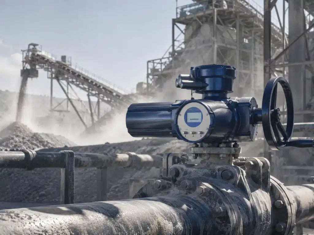
An actuator is a device that converts energy into mechanical movement. The energy source may be electricity, compressed air, hydraulic pressure or another form of stored energy, while the resulting movement can be rotational or linear.
In industrial systems, actuators are used whenever equipment needs to move automatically rather than by direct manual operation. Typical examples include operating valves, positioning dampers, moving gates, controlling machine components and adjusting process equipment.
In valve automation, the actuator provides the torque or thrust required to move the valve closure element. Ball valves and butterfly valves normally require rotational torque, while many globe valves, knife gate valves and other linear-stem valves require axial thrust.
Overview
Main Actuator Types at a Glance
The term actuator types can be confusing because actuators can be classified in more than one way. Electric and pneumatic describe the energy source, while rotary and linear describe the output movement.
| Actuator Type | Classification | Output | Typical Industrial Use |
|---|---|---|---|
| Electric Actuator | Power source | Rotary or linear movement | Remote valve automation, industrial equipment, water systems |
| Pneumatic Actuator | Power source | Rotary or linear movement | Process plants, frequent cycling, automated valves |
| Hydraulic Actuator | Power source | Rotary or linear movement | Very high-force or high-torque heavy-duty applications |
| Rotary Actuator | Motion type | Angular rotation | Ball valves, butterfly valves, dampers |
| Linear Actuator | Motion type | Straight-line movement | Globe valves, knife gate valves, positioning systems |
| Multi-Turn Actuator | Motion type | Multiple shaft rotations | Gate valves, globe valves and other multi-turn equipment |
Power Source
Actuator Types by Power Source
One of the most common ways to classify actuators is according to the energy source used to create mechanical movement.
Electric Actuators
Electric actuators use an electric motor to generate movement. A gearbox or drive mechanism converts motor speed into the torque, thrust and travel required by the connected equipment.
Industrial electric actuators are available in quarter-turn, multi-turn and linear configurations. Depending on the design, they can provide ON/OFF operation, modulating control, position feedback, manual override and communication with PLC, DCS or SCADA systems.
Electric actuation is particularly practical when electrical power is readily available but a compressed-air system is not. It is commonly used in water treatment plants, remote pipeline installations, industrial equipment and automated process systems.
Pneumatic Actuators
Pneumatic actuators use compressed air to generate movement. Air pressure acts on pistons, diaphragms or other mechanisms to create rotary torque or linear thrust.
Quarter-turn pneumatic actuators are commonly paired with ball valves and butterfly valves, while pneumatic cylinders and diaphragm actuators are widely used for linear valve movement.
Pneumatic actuator systems are especially common in process plants with an existing instrument-air network and in applications requiring fast movement, frequent cycling or mechanical spring-return fail-safe operation.
Hydraulic Actuators
Hydraulic actuators use pressurized fluid to produce mechanical movement. They can generate very high force or torque relative to their size and are therefore used in heavy-duty machinery, large pipeline systems and specialized industrial applications.
Because most Fleyenda valve automation applications focus on electric and pneumatic actuation, this guide concentrates primarily on those technologies rather than hydraulic systems.
Motion Classification
Actuator Types by Movement
Another important classification is the way the actuator moves its output shaft or stem. The three most important industrial motion categories are rotary, linear and multi-turn.
Rotary Actuator
A rotary actuator produces angular movement and rotational torque. Quarter-turn rotary actuators typically rotate approximately 90 degrees and are widely used on ball valves, butterfly valves, plug valves and dampers.
Rotary actuators can be electric, pneumatic or hydraulic. The correct type depends on torque, speed, available utilities and automation requirements.
Linear Actuator
A linear actuator produces movement in a straight line. Its primary mechanical output is normally expressed as thrust rather than torque.
Linear actuators are used where equipment must push, pull, lift or position something along a straight path. In valve automation, they are commonly associated with globe valves, diaphragm valves, knife gate valves and other linear-stem designs.
Multi-Turn Actuator
A multi-turn actuator rotates its output shaft through multiple complete revolutions. This movement is commonly used to operate gate valves and other valves where several stem rotations are required to complete the full travel.
Some multi-turn valves convert rotational actuator movement into linear movement through a threaded stem and nut arrangement.
Motion Comparison
Quarter-Turn vs Multi-Turn vs Linear Actuators
| Feature | Quarter-Turn | Multi-Turn | Linear |
|---|---|---|---|
| Movement | Usually approximately 90° | Multiple full rotations | Straight-line stroke |
| Main Output | Torque | Torque | Thrust |
| Typical Valves | Ball, butterfly and plug valves | Gate and selected globe valves | Globe, diaphragm and knife gate valves |
| Typical Power Source | Electric, pneumatic or hydraulic | Primarily electric or hydraulic | Electric, pneumatic or hydraulic |
| Key Sizing Parameter | Required torque | Torque, turns and operating time | Required thrust and stroke |
The required valve movement should normally be identified before choosing the actuator power source. Selecting the wrong motion type can make an otherwise correctly sized actuator unsuitable for the valve.
Electric Automation
Common Electric Actuator Types
Electric actuators can be further classified according to their movement and control capabilities.
01
Quarter-Turn Electric Actuator
Produces approximately 90° rotary movement for ball valves, butterfly valves, plug valves and dampers.
02
Multi-Turn Electric Actuator
Produces multiple output-shaft rotations for gate valves and other equipment requiring extended rotational travel.
03
Linear Electric Actuator
Converts motor rotation into straight-line movement for valves and industrial positioning applications.
04
ON/OFF Electric Actuator
Moves equipment between defined end positions such as fully open and fully closed.
05
Modulating Electric Actuator
Positions the output between end positions according to signals such as 4–20 mA or 0–10 V.
06
Intelligent Electric Actuator
Adds electronic monitoring, diagnostics, position control and, on selected models, industrial communication functions.
Pneumatic Automation
Common Pneumatic Actuator Types
Pneumatic actuators are commonly classified according to their mechanical design and failure behavior.
Double-Acting Pneumatic Actuator
A double-acting actuator uses compressed air to create movement in both directions. It is widely used for general industrial valve automation when mechanical spring-return action is not required.
Single-Acting Spring-Return Actuator
A spring-return pneumatic actuator uses compressed air for movement in one direction and stored spring force in the opposite direction. Depending on assembly and process requirements, it can be configured for fail-open or fail-close operation.
Rack-and-Pinion Actuator
A rack-and-pinion actuator uses pistons and gear racks to rotate a central pinion. It is compact and widely used for quarter-turn ball valve and butterfly valve automation.
Scotch-Yoke Actuator
A Scotch-yoke actuator converts linear piston movement into angular rotation through a yoke mechanism. This design can provide a torque profile suitable for larger valves and high-torque quarter-turn applications.
Valve Compatibility
Which Actuator Type Is Used for Each Valve?
The valve design determines the required motion first. The power source can then be selected according to site utilities, speed, failure behavior and control requirements.
| Valve Type | Required Motion | Common Actuator Types | Main Selection Factor |
|---|---|---|---|
| Ball Valve | Quarter-turn rotary | Electric or pneumatic | Breakaway torque, speed, fail position |
| Butterfly Valve | Quarter-turn rotary | Electric or pneumatic | Valve torque, size, pressure, operating speed |
| Plug Valve | Quarter-turn rotary | Electric or pneumatic | High breakaway torque may need consideration |
| Gate Valve | Multi-turn | Multi-turn electric actuator | Torque, stem travel and required number of turns |
| Globe Valve | Linear or multi-turn | Pneumatic linear or electric actuator | Thrust, stroke and control accuracy |
| Knife Gate Valve | Linear | Pneumatic cylinder or electric drive | Stroke, thrust, solids load and speed |
| Control Valve | Depends on valve design | Electric or pneumatic modulating actuator | Positioning accuracy and process dynamics |
Control Method
Actuator Types by Control Mode
ON/OFF Actuator
An ON/OFF actuator moves equipment between two primary positions. In a valve application, these are normally fully open and fully closed. This is the simplest type of automated valve control.
Modulating Actuator
A modulating actuator moves to intermediate positions according to a control signal. Electric actuators may use internal electronic control modules, while pneumatic actuators generally use a valve positioner.
Common industrial analog control signals include 4–20 mA and 0–10 V.
Intelligent Actuator
Intelligent actuators add functions such as electronic position monitoring, diagnostics, configurable operating parameters and digital communication. Available features vary significantly between actuator models.
Failure Strategy
Fail-Open, Fail-Close and Fail-in-Place Actuators
Actuator failure behavior describes what should happen when electrical power, pneumatic pressure or another energy source is lost.
Fail Close
The actuator system moves the valve toward the closed position after loss of the primary energy source. This may be required for fuel, chemical feed or other applications where continued flow creates a process risk.
Fail Open
The valve moves toward the open position after failure. Cooling-water, venting and other safety functions may require this philosophy depending on the process.
Fail in Place
The actuator remains approximately in its last position when energy is lost. This can be appropriate where maintaining the existing process condition is safer than automatically opening or closing the valve.
Spring-return pneumatic actuators provide a common mechanical method of achieving fail-open or fail-close behavior. Electric actuators require a suitable stored-energy, spring, capacitor, battery or backup-power design if automatic repositioning is required during power loss.
Mechanical Output
Torque vs Thrust: The Most Important Sizing Difference
Actuator sizing should begin with the mechanical output required by the equipment.
Rotary actuators are normally sized according to torque. Linear actuators are primarily selected according to thrust and stroke. Multi-turn actuators also require evaluation of torque, operating turns and travel time.
| Parameter | Used For | What It Represents |
|---|---|---|
| Torque | Rotary and multi-turn actuators | Rotational force available to turn a shaft |
| Thrust | Linear actuators | Push or pull force along a straight axis |
| Stroke | Linear actuators | Total linear movement required |
| Rotation Angle | Quarter-turn actuators | Total angular travel, commonly around 90° |
| Number of Turns | Multi-turn actuators | Total shaft rotations required to complete travel |
For valves, actual breakaway torque, running torque, seating torque, stem friction and differential pressure should be considered rather than selecting an actuator only according to nominal valve diameter.
Selection Guide
How to Choose Between Different Actuator Types
A reliable actuator selection process starts with the equipment and process requirements rather than with a specific actuator model.
01
Identify the Required Motion
Determine whether the application requires quarter-turn rotary movement, multiple shaft rotations or linear movement.
02
Calculate Torque or Thrust
Use actual equipment load data and evaluate the most demanding expected operating condition.
03
Check Available Utilities
Determine whether electrical power, compressed air or another energy source is readily available at the installation point.
04
Define Operating Speed
Specify how quickly the actuator should complete its travel without creating unwanted process effects.
05
Confirm Operating Frequency
Determine whether the actuator will operate occasionally, cycle frequently or continuously modulate during production.
06
Define the Failure Position
Specify whether the equipment should fail open, fail closed or remain in its last position.
07
Select the Control Mode
Choose simple ON/OFF operation, analog modulating control or intelligent digital control according to the automation system.
08
Check Environmental Conditions
Consider rain, washdown, dust, corrosion, ambient temperature and hazardous-area requirements.
09
Confirm the Mounting Interface
Check shaft dimensions, mounting flange, coupling and applicable actuator-interface standards.
10
Compare Lifecycle Requirements
Evaluate installation infrastructure, maintenance capability, energy supply and spare-part requirements rather than purchase price alone.
Decision Factors
Electric vs Pneumatic Actuators: Which Type Should You Choose?
Electric and pneumatic actuators are both widely used in industrial automation, but their advantages depend heavily on the installation.
| Factor | Electric Actuator | Pneumatic Actuator |
|---|---|---|
| Energy Source | Electrical power | Compressed air |
| Installation | Power and signal wiring | Air tubing plus pneumatic accessories |
| Fast Cycling | Depends heavily on model and duty rating | Often well suited when the air system is correctly sized |
| Spring Fail-Safe | Requires suitable fail-safe actuator design | Spring-return designs are widely available |
| Modulating Control | Electronic control module | Pneumatic or electro-pneumatic positioner |
| Remote Locations | Practical where electrical power is available | Requires reliable compressed-air distribution |
| Maintenance Focus | Electrical components, motor and gearbox | Air quality, seals, tubing and control accessories |
Neither actuator type is universally better. A facility with an established instrument-air network may benefit from pneumatic actuation, while a remote installation with electrical power but no compressed-air infrastructure may favor electric actuation.
Operating Environment
IP Ratings, Outdoor Service and Explosion-Proof Actuators
The actuator type must also match the environment in which it operates. Outdoor valves, washdown areas, chemical plants and hazardous locations place different demands on actuator housings and electrical equipment.
IP67 and IP68
Ingress protection ratings describe resistance to dust and water under defined test conditions. The required level should be selected according to the actual installation rather than simply choosing the highest available rating.
Explosion-Protected Actuators
Hazardous-area installations may require specially certified electrical equipment. This includes electric actuators as well as electrical accessories installed on pneumatic actuator packages, such as solenoid valves, limit switch boxes and positioners.
Corrosive Environments
Housing material, protective coating, fasteners, cable entries and accessories should also be evaluated where the actuator is exposed to salt, chemicals or corrosive industrial atmospheres.
Common Mistakes
Common Actuator Selection Mistakes
Choosing by Valve Size Alone
Two valves with the same nominal diameter can require very different actuator torque because of seat design, pressure and valve construction.
Confusing Power Type with Motion Type
Electric and pneumatic describe how the actuator is powered, while rotary and linear describe how it moves.
Ignoring Minimum Air Pressure
Pneumatic actuator output should be checked at the minimum reliable pressure available at the actuator location.
Ignoring Electric Duty Cycle
An electric actuator selected for occasional isolation may not be suitable for continuous or frequent modulating service.
Using One Fixed Torque Safety Factor
The appropriate actuator margin depends on actual valve torque, pressure, medium, deposits, temperature and service conditions.
Forgetting the Failure Position
Fail-open, fail-close or fail-in-place requirements should be defined before the actuator package is selected.
Selecting the Fastest Actuator
Fast operation can be useful, but excessive closing speed can create pressure surge or other process problems.
Ignoring Accessories
Solenoid valves, positioners, limit switches, regulators and control modules can be essential parts of the complete automation package.
Fleyenda Actuator Solutions
Industrial Actuator Types Available from Fleyenda
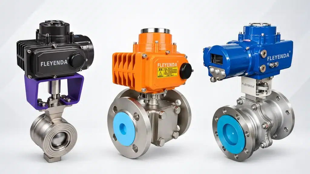
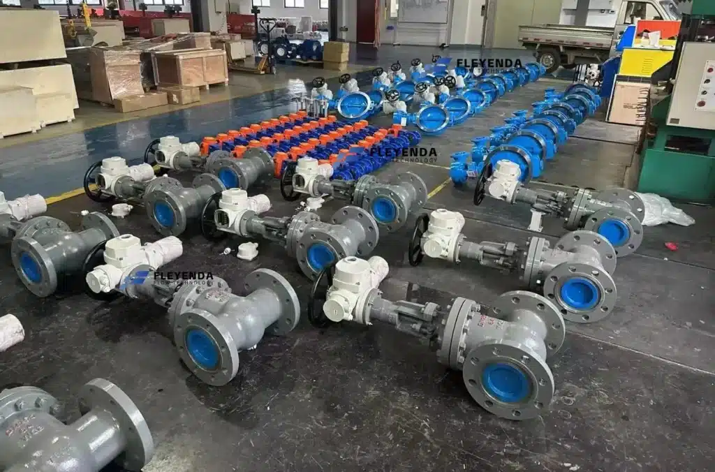
Fleyenda focuses on electric and pneumatic actuator solutions for industrial valve automation, including quarter-turn, multi-turn, ON/OFF, modulating, intelligent and high-torque actuator configurations.
Electric · Quarter-Turn
FLE Series Electric Actuator
A compact quarter-turn electric actuator series for compatible ball valves, butterfly valves and dampers.
- 0–90° quarter-turn operation
- 50–3000 Nm listed torque range
- ON/OFF and modulating control
- 4–20 mA / 0–10 V options
- ISO 5211 mounting interface
Electric · Multi-Turn
Z Series Multi-Turn Electric Actuator
A multi-turn electric actuator series for valves and equipment requiring multiple output-shaft rotations.
- Multi-turn movement
- 50–3000 Nm listed torque range
- ON/OFF, regulating and intelligent options
- 4–20 mA / 0–10 V / Modbus options
- ISO 5210 mounting interface
Pneumatic · High Torque
AW Series Scotch-Yoke Pneumatic Actuator
A heavy-duty pneumatic actuator series for high-torque quarter-turn applications including suitable large ball valves and butterfly valves.
- Scotch-yoke mechanism
- 90° quarter-turn movement
- Double acting or spring return
- Fail-close / fail-open configurations
- High-torque industrial applications
FAQ
Frequently Asked Questions About Actuator Types
What are the main actuator types?
The main industrial actuator types are electric, pneumatic and hydraulic when classified by power source, and rotary, linear and multi-turn when classified by movement.
What are the most common actuator types for valves?
Electric and pneumatic actuators are among the most common choices for industrial valve automation. Quarter-turn actuators are widely used on ball and butterfly valves, while multi-turn and linear actuators are used on gate, globe and other linear-stem valves.
What is the difference between a rotary and linear actuator?
A rotary actuator creates angular movement and torque, while a linear actuator creates straight-line movement and thrust.
What is a quarter-turn actuator?
A quarter-turn actuator typically rotates approximately 90 degrees and is commonly used to automate ball valves, butterfly valves and plug valves.
What is a multi-turn actuator?
A multi-turn actuator produces multiple complete shaft rotations and is commonly used for gate valves and other equipment requiring extended rotational travel.
What is the difference between electric and pneumatic actuators?
Electric actuators use electrical power and a motor, while pneumatic actuators use compressed air. The better choice depends on available utilities, operating speed, failure strategy, cycling frequency and control requirements.
Which actuator type is best for a ball valve?
Ball valves normally use quarter-turn rotary actuators. Both electric and pneumatic designs are widely used, and the correct choice depends on required torque, speed, fail position and site utilities.
Which actuator type is used for butterfly valves?
Butterfly valves typically use quarter-turn electric or pneumatic rotary actuators.
Which actuator type is used for gate valves?
Automated gate valves commonly use multi-turn electric actuators because the valve stem typically requires multiple rotations to complete its travel.
How do I choose the correct actuator type?
Start with the required movement, torque or thrust, then evaluate available utilities, operating speed, frequency, failure position, control signal, environment and mounting interface.
Can the same actuator type provide both ON/OFF and modulating control?
Yes. Many electric and pneumatic actuator families are available in both ON/OFF and modulating configurations, although the required control components differ.
What information is required to size a valve actuator?
Useful information includes valve type and size, process medium, pressure, differential pressure, temperature, required torque or thrust, operating frequency, desired travel time, available power or air pressure, control mode and required failure position.
Conclusion
Choose the Actuator Type Around the Required Motion and Process
Understanding actuator types begins with separating power-source classifications from motion classifications. Electric and pneumatic describe how an actuator receives energy, while rotary, linear and multi-turn describe how that energy is converted into mechanical movement.
For industrial valve automation, the correct actuator should be selected according to valve movement, required torque or thrust, operating speed, duty cycle, available utilities, control requirements, failure position and installation environment.
Fleyenda provides electric and pneumatic actuator solutions for quarter-turn, multi-turn, ON/OFF, modulating and high-torque industrial valve automation applications.