


Motorized Ball Valve Guide
A motorized ball valve is a quarter-turn ball valve operated automatically by an electric actuator. Instead of using a manual handle, the actuator receives an electrical command and rotates the valve ball to open, close, divert or regulate fluid flow.
Motorized ball valves are widely used in water treatment, HVAC systems, industrial automation, chemical processing, oil and gas systems, equipment manufacturing and other applications where remote valve operation or automatic process control is required.
Definition
What Is a Motorized Ball Valve?
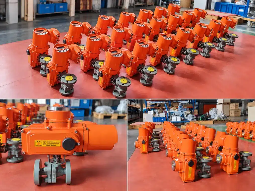
A motorized ball valve, also called an electric actuated ball valve or electric ball valve, is an automated flow-control device consisting of a ball valve and an electric actuator. The actuator replaces the manual lever normally used to rotate the valve stem.
Inside the valve body is a spherical closure element with a bore through its center. When the bore aligns with the pipeline, fluid can flow through the valve. When the ball rotates approximately 90 degrees, the solid side of the ball moves across the flow path and shuts off the pipeline.
The electric actuator converts electrical energy into rotary mechanical movement. Internal gears reduce motor speed and increase output torque before transferring that torque through the actuator output shaft to the valve stem.
This combination makes a motorized ball valve useful wherever operators need automatic shutoff, remote operation, PLC control or repeatable valve positioning without manually operating the valve.
Working Principle
How Does a Motorized Ball Valve Work?
The working principle of a motorized ball valve is based on quarter-turn rotation. When the control system sends an open command, the electric actuator motor starts and transfers rotational force through its gearbox. The actuator output shaft rotates the valve stem, which turns the internal ball.
In a standard 2-way ball valve, the valve is fully open when the bore through the ball is aligned with the pipe. To close the valve, the actuator rotates the ball approximately 90 degrees until the solid surface of the ball blocks the flow passage.
Limit switches, position sensors or the actuator control electronics stop the motor when the required position is reached. In many ON/OFF designs, the actuator therefore consumes power mainly while moving rather than continuously consuming power to hold the valve mechanically in position.
01Control Signal
A PLC, switch, relay, controller or process instrument sends an operating command.
02Electric Motor
The motor converts electrical energy into rotational motion.
03Gear Reduction
The gearbox reduces speed and increases the torque available to operate the valve.
04Valve Rotation
The actuator rotates the stem and ball toward the required position.
05Position Control
Limit switches or position electronics stop and confirm the final valve position.
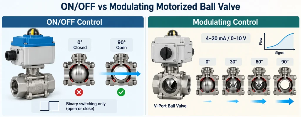
A modulating motorized ball valve works on the same basic principle but does not operate only at 0% and 100%. The actuator can stop at intermediate positions according to a control signal such as 4–20 mA or 0–10 V.
Construction
Main Components of a Motorized Ball Valve
| Component | Function | What to Check |
|---|---|---|
| Valve Body | Contains the pressure boundary and flow passage. | Material, pressure rating, size and connection type. |
| Ball | Rotates to open, close or redirect the flow path. | Full-port or reduced-port design and material compatibility. |
| Valve Seat | Provides sealing around the ball. | PTFE or other seat material according to medium and temperature. |
| Stem | Transfers actuator torque to the ball. | Mechanical strength, sealing and corrosion resistance. |
| Electric Actuator | Generates the rotational torque required to move the ball. | Torque, voltage, duty, control type and enclosure rating. |
| Limit / Position System | Stops movement and confirms valve position. | Open/close feedback and PLC compatibility. |
| Manual Override | Allows local operation if electrical power or control is unavailable. | Required accessibility and operating method. |
Valve Types
Types of Motorized Ball Valves
2-Way Motorized Ball Valve
A 2-way motorized ball valve has one inlet and one outlet and is primarily used for automatic pipeline isolation. It is the most common configuration for water treatment equipment, HVAC piping, industrial utility systems and process lines.
3-Way Motorized Ball Valve
A 3-way motorized ball valve contains three ports and is used to redirect, distribute, bypass or, in selected configurations, mix flow. L-port and T-port ball designs provide different flow paths, so the required routing logic should be confirmed before ordering.
Full-Port Motorized Ball Valve
A full-port ball valve has a bore close to the internal pipe diameter. This provides relatively low flow restriction and is useful where maintaining flow capacity is important. Reduced-port designs can be smaller and more economical but produce a greater restriction in the flow path.
Threaded Motorized Ball Valve
Threaded motorized ball valves are commonly used in compact equipment, skid systems and smaller process pipelines. They provide convenient installation where threaded connections such as BSP or NPT are specified.
Flanged Motorized Ball Valve
Flanged electric ball valves are widely used in industrial process piping because the flange connection provides robust mechanical installation and makes the valve suitable for larger pipe sizes and higher-duty service.
Sanitary Motorized Ball Valve
Sanitary motorized ball valves use hygienic connections and materials such as stainless steel to support food, beverage, pharmaceutical and hygienic process applications where cleanability is important.
Plastic or UPVC Motorized Ball Valve
UPVC electric ball valves are useful for compatible corrosive liquids, purified water, weak acids, alkalis and selected water-treatment chemicals where metallic valve materials may not be the preferred option.
Control Methods
ON/OFF vs Modulating Motorized Ball Valves
| Feature | ON/OFF Motorized Ball Valve | Modulating Motorized Ball Valve |
|---|---|---|
| Valve Position | Fully open or fully closed | Intermediate positions available |
| Typical Signal | Open / close command | 4–20 mA or 0–10 V |
| Main Duty | Isolation and automatic shutoff | Flow or process regulation |
| Typical Application | Tank filling, equipment isolation, pipeline switching | Process control, temperature control, flow adjustment |
| Selection Focus | Torque, operating time and feedback | Torque, positioning accuracy and control compatibility |
An important distinction is that simply stopping a standard ball valve at a partially open angle does not automatically make it an ideal control valve. Where accurate and repeatable throttling is required, a V-port ball valve or another valve designed for modulating service may provide better control characteristics.
Comparison
Motorized Ball Valve vs Solenoid Valve
Motorized ball valves and solenoid valves can both automate fluid control, but they operate differently and are suited to different applications.
| Factor | Motorized Ball Valve | Solenoid Valve |
|---|---|---|
| Operating Principle | Electric motor rotates a mechanical ball valve. | Electromagnetic coil moves an internal plunger or pilot mechanism. |
| Typical Pipe Size | Suitable from small process lines to comparatively larger pipelines. | Commonly used in smaller lines and fast switching applications. |
| Flow Path | Full-port designs can provide relatively low restriction. | Internal passages may create greater restriction depending on design. |
| Closing Speed | Usually slower than a typical direct-acting solenoid valve. | Can switch very quickly. |
| Power | Many designs primarily consume power during movement. | Some designs require the coil to remain energized in one state. |
| Modulating Control | Available with suitable actuator and valve configuration. | Requires a proportional solenoid design rather than a standard ON/OFF unit. |
A slower closing time can reduce hydraulic shock in some water systems compared with very rapid shutoff, but a motorized ball valve should not be assumed to eliminate water hammer. Pipeline velocity, pipe length, pump operation, valve operating time and overall hydraulic design must all be considered.
Actuator Sizing
How to Select the Correct Motorized Ball Valve Actuator
Actuator sizing is one of the most important parts of motorized ball valve selection. The actuator must generate enough output torque to operate the valve under actual process conditions rather than only under ideal workshop conditions.
Start with the valve manufacturer’s required operating torque. Then consider factors that can increase torque during service, including maximum differential pressure, seat material, valve size, medium viscosity, temperature, deposits, operating frequency and long periods without movement.
A design margin is normally applied between required valve torque and actuator output torque, but there is no single safety factor that is correct for every valve. The appropriate margin should be based on the valve manufacturer’s torque data, actuator characteristics and process conditions.
Before selecting actuator torque, confirm:Valve size · valve design · maximum differential pressure · seat material · fluid viscosity · operating temperature · operating frequency · required fail-safe behavior · available power supply.
Duty Cycle
Why Actuator Duty Cycle Matters
Duty cycle describes how frequently an actuator can operate without exceeding its thermal limitations. It becomes particularly important when a motorized ball valve operates repeatedly in an automated process.
An isolation valve that moves only several times per day may place relatively little thermal demand on the actuator. A modulating or frequently cycling valve can operate much more often and therefore requires an actuator designed for the expected operating frequency.
Do not assume that every AC actuator has the same duty rating or that every DC actuator can operate continuously. Duty cycle varies by actuator model, motor design, load and ambient temperature. Always verify the manufacturer’s rated operating duty for the actual actuator.
Electrical Control
Motorized Ball Valve Wiring, Feedback and PLC Integration
Motorized ball valves can be supplied with different wiring and control arrangements. There is no universal wiring diagram for every electric actuator, so the electrical drawing supplied with the selected actuator should always be followed.
ON/OFF Control
Basic ON/OFF actuators receive an electrical command to rotate the valve between the fully open and fully closed positions. Common control arrangements include separate open and close commands or power-based return logic depending on actuator design.
Open / Close Position Feedback
Auxiliary limit switches or dry contacts can provide open and closed position feedback to a PLC or control panel. This allows the control system to confirm that the commanded valve movement has actually been completed.
Modulating Control
Modulating actuators can accept analog control signals such as 4–20 mA or 0–10 V and position the valve according to the input command. Position feedback may also be provided to the control system.
Industrial Communication
More advanced actuator configurations may support digital communication or intelligent control functions. Where protocols such as Modbus are required, communication compatibility should be confirmed before ordering.
Common industrial actuator power options include DC24V, AC110V and AC220V. The correct voltage should always match the site’s available power supply and control architecture.
Power Failure
What Happens to a Motorized Ball Valve When Power Fails?
The answer depends on the actuator design. Some electric actuators remain in their last position when power is lost, while fail-safe actuators use stored mechanical or electrical energy to move the valve to a predetermined safe position.
Possible strategies include spring-return actuators, capacitor or battery-assisted return systems and other emergency-return designs. The correct fail position is application-specific. Some processes require fail-close, while others require fail-open or fail-in-place operation.
A manual override can also be valuable for critical installations because it allows maintenance personnel to operate the valve locally when electrical power or automatic control is unavailable.
Materials
How to Choose Motorized Ball Valve Materials
| Material | Typical Use | Selection Consideration |
|---|---|---|
| Stainless Steel 304 | Water, industrial fluids and general process service | Good general corrosion resistance |
| Stainless Steel 316 / 316L | Chemical, food, process and more corrosive environments | Improved corrosion resistance compared with 304 in many applications |
| Carbon Steel | Industrial oil, gas and process piping | Requires compatibility assessment and suitable corrosion protection |
| UPVC | Water treatment, saline water and compatible chemical solutions | Temperature and pressure limits are lower than many metal valves |
| PTFE Seat | Common industrial ball valve sealing | Check temperature, pressure and chemical compatibility |
Material selection should always be based on the actual medium rather than the industry name alone. Two water-treatment plants, for example, may require different valve materials if one line carries clean water while another carries concentrated treatment chemicals.
Applications
Where Are Motorized Ball Valves Used?
Water Treatment
Automatic isolation, filter systems, dosing equipment, process water and treatment skids.
HVAC Systems
Hot and chilled water circuits, zone control and automatic equipment isolation.
Industrial Automation
PLC-controlled production equipment, utility lines, tank filling and automated process skids.
Chemical Processing
Automated control of compatible chemical liquids using suitable body and seat materials.
Oil and Gas
Remote isolation, utility systems and process pipelines where electric automation is required.
Food and Beverage
Sanitary process lines using hygienic stainless-steel ball valve configurations.
Fleyenda Selection
Motorized Ball Valve Options from Fleyenda
Fleyenda provides electric ball valve configurations for general industrial isolation, compact equipment, flow diversion, water treatment and corrosive-service applications.
Flanged Industrial Valve
FLE-Q-F Electric 2-Way Flange Ball Valve
Stainless-steel flanged motorized ball valve for automated water, oil, gas, chemical and industrial process pipelines. Available for DN15–DN300 with PN16–PN40 pressure options.
Serviceable Compact Design
FLE-Q-3PS 3-Piece Motorized Ball Valve
A service-friendly stainless-steel three-piece valve designed for equipment, utility and industrial process lines where access to internal seats and seals is important.
Flow Diversion
FLE-Q-TF Electric 3-Way Flanged Ball Valve
L-port and T-port configurations for automated diversion, distribution, bypass and selected mixing duties in industrial piping systems.
Water & Corrosive Service
UPVC Electric 2-Way Ball Valve
UPVC body construction for compatible corrosive liquids, weak acids, alkalis, saline water and water-treatment applications.
Selection Guide
How to Choose a Motorized Ball Valve
01
Define the Valve Function
Determine whether the valve is required for shutoff, diversion or modulating control.
02
Confirm Valve Size
Match the required DN or inch size and determine whether full-port flow is necessary.
03
Check Pressure
Confirm system pressure and maximum differential pressure across the valve.
04
Identify the Medium
Specify water, oil, gas, steam, chemical liquid or other media to select compatible materials.
05
Confirm Temperature
Check both process temperature and actuator ambient temperature.
06
Select Connection
Choose threaded, flanged, welded, sanitary or another connection according to the piping system.
07
Select Control Mode
Choose ON/OFF, modulating or intelligent control according to the automation requirement.
08
Confirm Voltage
Match the actuator voltage to the site’s electrical supply.
09
Specify Feedback
Confirm whether the PLC requires open/close feedback or continuous position feedback.
10
Check Environment
Specify indoor, outdoor, washdown or hazardous-area installation requirements.
Common Mistakes
Motorized Ball Valve Selection Mistakes to Avoid
Choosing the Actuator Only by Valve Size
Two valves of the same nominal size can require different torque because of seat design, pressure, material and operating conditions.
Ignoring Differential Pressure
Actuator sizing should reflect the actual pressure load across the closed valve, not only the nominal pipeline rating.
Using an ON/OFF Ball Valve for Precise Throttling
For continuous regulation, use a suitable modulating valve design such as a V-port ball valve when appropriate.
Ignoring Duty Cycle
A valve that cycles frequently may require a different actuator from one that operates only occasionally.
Assuming Every Wiring Method Is the Same
Terminal arrangement and feedback wiring vary by actuator model. Always follow the actual actuator wiring diagram.
Forgetting the Failure Position
Critical applications should define what the valve must do when electrical power or control signals are lost.
FAQ
Frequently Asked Questions About Motorized Ball Valves
What is a motorized ball valve?
A motorized ball valve is a ball valve operated automatically by an electric actuator. The actuator rotates the valve stem and ball to open, close or regulate the fluid path.
What is the difference between an electric ball valve and a motorized ball valve?
In industrial usage, the terms are often used interchangeably. Both generally describe a ball valve operated by an electric actuator rather than a manual handle.
Does a motorized ball valve need power all the time?
Not necessarily. Many electric actuators consume power mainly while moving and stop the motor after reaching the commanded position. The exact behavior depends on actuator design and control method.
Can a motorized ball valve control flow?
Yes, but the valve and actuator should be designed for modulating service. A V-port ball valve is often more suitable than a standard full-port ball valve when accurate flow regulation is required.
What voltage does a motorized ball valve use?
Common industrial options include DC24V, AC110V and AC220V, although other voltages are available. Voltage must match the site’s electrical system and actuator specification.
Can a motorized ball valve provide PLC feedback?
Yes. Suitable actuators can provide open/close limit feedback, dry contacts or analog position feedback for PLC, DCS or other control systems.
What happens if power fails?
A standard actuator may remain in its last position. Fail-safe actuator configurations can move the valve to a predefined open or closed position using spring, capacitor or another stored-energy system.
Is a motorized ball valve suitable for outdoor installation?
Yes, provided that the actuator enclosure, materials and electrical protection are suitable for the actual environment. Outdoor and wet installations should use an appropriate IP protection rating.
Conclusion
Choosing the Right Motorized Ball Valve Starts with the Application
A motorized ball valve is more than a manual ball valve with a motor attached. Reliable automation depends on matching the valve body, ball and seat materials, connection, actuator torque, voltage, operating duty, feedback and failure behavior to the real process conditions.
For simple pipeline isolation, an ON/OFF 2-way motorized ball valve may be sufficient. Flow routing may require a 3-way L-port or T-port valve, while continuous regulation may require a V-port ball valve with a modulating actuator.
Fleyenda supplies electric ball valve solutions for water treatment, industrial automation, chemical processing, HVAC, oil and gas and equipment applications. Send us your valve size, medium, pressure, temperature, voltage and control requirements for application-specific selection support.