


Motorized Ball Valve for Pump Systems
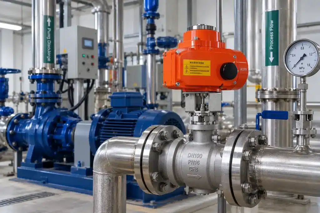
A motorized ball valve can do much more in a pump system than simply open or close a pipeline. Depending on valve design and control strategy, it can isolate a pump, control discharge flow, redirect liquid between lines, regulate a bypass circuit or become part of an automated pump startup and shutdown sequence.
The challenge is that pump systems are dynamic. Pressure and flow change rapidly when the pump starts, stops or moves to a different operating point. A valve that is sized only by pipe diameter may operate correctly under static conditions but create excessive pressure loss, water hammer, unstable control or actuator overload once the pump is running.
Correct motorized ball valve selection therefore requires more than matching DN and pressure class. Valve function, actuator torque, operating speed, differential pressure, control signal, fail-safe behavior and pump sequence all need to be considered together.
This becomes especially important in pump skids, water treatment plants, industrial circulation systems and automated process lines where valves and pumps are controlled from the same PLC or DCS.
The first question should not be “What size motorized ball valve fits this pipe?” It should be “What must the valve do during pump startup, normal operation and shutdown?”
What Does a Motorized Ball Valve Do in a Pump System?
The role of a motorized ball valve depends on where it is installed and how the control system uses it.
In the simplest application, the valve provides automatic isolation. The PLC commands the valve to open before the pump starts and confirms that the required flow path is available through position feedback.
In more advanced systems, a motorized ball valve can divert pump discharge between tanks, switch duty and standby lines, control a recirculation path or modulate the amount of liquid delivered to a process.
These functions place very different demands on the valve. An isolation valve normally spends most of its life fully open or fully closed, while a control valve may continuously move between intermediate positions.
Isolation Valve or Flow-Control Valve?
This distinction should be made before actuator selection.
A standard full-port motorized ball valve is well suited to automatic isolation because the open flow path creates relatively low hydraulic resistance and the quarter-turn mechanism provides reliable shut-off.
However, a conventional round-port ball valve is not always the best choice for continuous throttling. The relationship between ball position and flow area is nonlinear, especially near the closed position.
If the pump system requires accurate flow, pressure or bypass regulation, a motorized V-port ball valve is usually more appropriate. The V-shaped opening provides a more predictable change in effective flow area as the valve moves.
| Valve Function | Typical Valve Choice | Main Requirement |
|---|---|---|
| Pump isolation | Full-port motorized ball valve | Low pressure loss and reliable shut-off |
| Discharge flow regulation | V-port motorized ball valve | Stable modulating control |
| Minimum-flow bypass | V-port or suitable control valve | Repeatable low-flow control |
| Flow diversion | Motorized 3-way ball valve | Correct routing between pipelines |
| Emergency isolation | Actuated isolation ball valve | Defined closing logic and fail action |
Motorized Ball Valves on the Pump Suction Side
A valve installed on the suction side of a centrifugal pump should normally create as little flow restriction as practical during operation.
Excessive pressure loss before the pump reduces the available suction pressure and can reduce the margin between available NPSH and the pump’s required NPSH.
For this reason, a suction isolation valve is commonly selected as a full-port design and operated fully open while the pump is running.
Using a standard ball valve to throttle pump suction is generally undesirable because the restriction can increase the risk of cavitation and unstable pump operation.
If a motorized ball valve is used on the pump suction line, treat it primarily as an isolation device unless the complete suction hydraulics have been specifically engineered for another function.
Motorized Ball Valves on the Pump Discharge Side
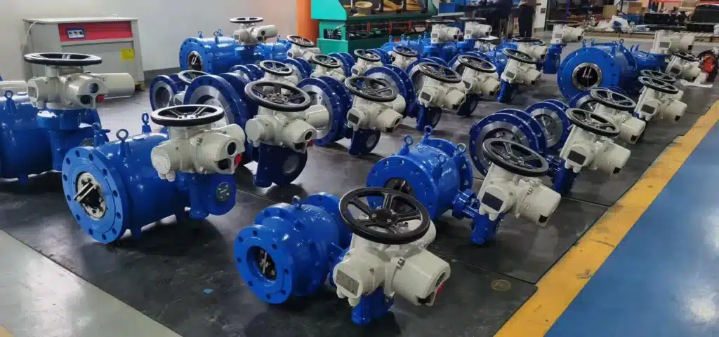
The discharge side gives engineers more control options because positive pressure is already available from the pump.
A motorized ball valve may isolate the pump from the downstream header, control delivery to a process line or work together with a check valve during startup and shutdown.
Where the valve is used only for isolation, pressure loss in the fully open position should be minimized.
Where discharge flow must be continuously controlled, the valve should be selected for throttling duty. A V-port segmented ball valve can provide a more useful relationship between actuator position and flow than a standard round-port ball valve.
How Should a Motorized Ball Valve Work During Pump Startup?
Pump startup logic depends on the type of pump and process, but the motorized valve should be treated as part of the sequence rather than as an independent device.
The control system may need confirmation that an isolation valve is fully open before allowing the pump motor to start. In other systems, a discharge control valve may begin at a predefined position and then move according to pressure or flow demand.
Example Automated Startup Logic
Confirm that the suction path is open and the pump is ready for operation.
Command the required motorized ball valve to its startup position.
Verify valve position through open/close feedback or analogue position feedback.
Start the pump only after the required interlocks are satisfied.
Move a modulating valve toward the required flow or pressure setpoint if process control is needed.
The actual sequence should always follow pump manufacturer requirements and the hydraulic design of the system.
Motorized Ball Valve Control During Pump Shutdown
Shutdown deserves as much attention as startup because rapid changes in pump discharge flow can create pressure transients.
If a motorized ball valve closes before the pump has been stopped or slowed appropriately, the pump may temporarily operate against a restricted or closed discharge.
If the pump stops first while the valve remains open, reverse flow may occur unless a properly selected check valve prevents it.
The correct shutdown sequence therefore depends on the pump curve, check valve behavior, line length, downstream pressure and required valve closing time.
Motorized Ball Valve Closing Time and Water Hammer
Water hammer is one of the main reasons not to specify the fastest possible actuator without considering system hydraulics.
When a moving liquid is decelerated rapidly, its momentum creates a pressure wave that travels through the pipeline. The magnitude of the transient depends on fluid velocity, pipeline length, pipe elasticity, wave speed and how quickly the valve changes the effective flow area.
A ball valve is especially important in this discussion because the final part of closing can produce a substantial reduction in flow area over a relatively small amount of angular travel.
Increasing actuator closing time can reduce the rate of flow change in some systems, but closing time alone does not solve every surge problem. Check-valve dynamics, air pockets, pump inertia and pipeline geometry also contribute.
When Should a Pump System Use a V-Port Motorized Ball Valve?
A V-port motorized ball valve becomes useful when the pump system needs controlled variation rather than simple isolation.
The V-shaped opening creates a progressive change in flow area as the ball rotates. This makes intermediate valve positions more useful for regulating flow than the geometry of a conventional round-port ball valve.
Typical applications include pump discharge flow control, header-pressure regulation, minimum-flow recirculation, tank filling and process feed control.
In these applications, the electric actuator normally receives a modulating command such as 4–20 mA or another compatible control signal and moves the valve to the required intermediate position.
FLE-VQ-F Motorized V-Port Ball Valve for Pump Control
A dedicated motorized control valve for pump systems requiring accurate flow regulation, bypass control and process adjustment.
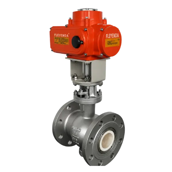
The FLE-VQ-F combines a segmented V-port ball valve with an electric actuator for proportional flow regulation. Unlike a standard round-port ball valve, the V-shaped opening provides a more progressive relationship between valve position and effective flow area.
In pump systems, it can be used for discharge-flow regulation, pressure-control loops, minimum-flow bypass and recirculation duties where accurate intermediate positioning is required.
Multiple V-port geometries and modulating actuator configurations allow the valve to be matched to different pump flow-control requirements.
| Size Range | DN25–DN300 / 1″–12″ | Pressure Options | PN16–PN40 / Class 150–300 |
| Body Materials | CF8 / CF8M / WCB | Connection | ANSI / DIN / JIS flanged |
| Voltage Options | DC24V / AC110V / AC220V / AC380V | Control Options | On-off / regulating / intelligent |
| Protection | IP67 standard / IP68 optional | V-Port Options | 15° / 30° / 60° / 90° |
Motorized Ball Valves for Pump Bypass and Recirculation
Some centrifugal pumps require a minimum flow to prevent overheating, internal recirculation or unstable operation at very low flow rates.
A controlled bypass line can return part of the pump discharge to the source vessel or another suitable location when process demand falls below the required minimum.
Where the bypass flow varies continuously, a modulating V-port motorized ball valve can be considered as part of the control loop.
The valve must still be properly sized. A bypass valve that is too large may operate almost completely closed during normal regulation, reducing controllability and increasing velocity through the restricted opening.
How Much Actuator Torque Does a Pump-System Ball Valve Need?
Electric actuator torque should be selected from the actual valve torque requirement rather than valve diameter alone.
Ball valve torque is affected by seat friction, differential pressure, valve size, temperature, seat material and the condition of the process medium.
Breakaway torque can be particularly important because a valve may remain stationary for long periods before the pump sequence requires movement.
A valve that operates correctly during dry testing may require significantly more torque when the pump produces full process pressure.
Size the actuator for the maximum realistic valve torque under process pressure, not for the torque measured on an unloaded valve during workshop testing.
How Fast Should a Motorized Ball Valve Operate in a Pump System?
There is no universal opening or closing time for pump applications.
A compact skid with short piping can tolerate a very different valve response from a long water-transfer line with high liquid velocity.
Fast actuation may reduce machine-cycle time or provide rapid isolation, but unnecessary speed can increase hydraulic transients.
Slower operation may provide smoother changes in flow, although an actuator that is too slow can delay pump sequencing or emergency response.
Valve speed should therefore be selected from the hydraulic and process requirements rather than treated as a standalone actuator feature.
Position Feedback and Pump Interlocks
Automated pump systems should not assume that a valve has moved simply because the control signal was sent.
Open and closed limit switches can confirm the end positions of an on-off motorized ball valve.
Modulating valves can provide continuous position feedback so the control system knows the actual valve opening.
This feedback can be incorporated into pump interlocks. For example, the PLC can prevent pump startup until a discharge isolation valve has confirmed its required position.
A mismatch between commanded position and actual position can also be used to trigger an alarm or stop the pump sequence.
What Should a Motorized Ball Valve Do During Power Failure?
A standard electric actuator normally requires power to move. If supply power is lost, it may remain in its current position unless a dedicated fail-safe function is provided.
The correct response depends on the pump process.
A chemical-feed pump may require the valve to close to stop uncontrolled transfer. A cooling-water system may require a different safety philosophy.
Fail-open, fail-close or stay-in-place behavior should therefore be defined during the process design stage rather than after the actuator has already been selected.
Cavitation, Pressure Drop and Pump Control Valves
A control valve converts pressure energy into velocity and turbulence as the flow passes through the restricted opening.
If local pressure falls below the liquid vapor pressure, vapor bubbles can form. When pressure recovers downstream, these bubbles can collapse and cause cavitation damage.
High differential pressure across a partially open valve also creates high local velocities that can accelerate seat and trim wear.
A V-port valve provides improved controllability, but it does not eliminate the need to check pressure-drop conditions.
Severe pressure-reduction duties should be evaluated with actual process data, including upstream pressure, downstream pressure, temperature and required flow range.
How to Size a Motorized Ball Valve for Pump Control
A control valve should not automatically be selected at the same nominal size as the pipeline.
For modulating pump control, the required flow coefficient should be calculated from the expected flow range and pressure drop.
Oversizing is a common problem. If the valve has far more capacity than required, normal control may occur close to the closed position, where small actuator movements can create large changes in flow.
An appropriately sized V-port valve allows a useful portion of the actuator travel to be used across the normal operating range.
| Selection Parameter | What to Check | Why It Matters |
|---|---|---|
| Flow Range | Minimum, normal and maximum flow | Determines required control capacity |
| Upstream Pressure | Pump discharge pressure | Defines available pressure energy |
| Downstream Pressure | Process or header pressure | Determines valve differential pressure |
| Valve Cv / Kv | Required flow coefficient | Determines control-valve size |
| Valve Torque | Maximum operating torque | Determines actuator output |
| Closing Time | Required hydraulic response | Affects pressure transient |
| Control Signal | On-off, 4–20 mA or other signal | Determines actuator control configuration |
Materials and Seat Selection for Pump-System Ball Valves
Water is only one of many liquids handled by pump systems. Chemical liquids, hydrocarbons, hot water, slurry, pulp and process fluids can place very different demands on the valve.
Body material should be selected for corrosion resistance, pressure and temperature. Stainless-steel grades can be useful in corrosive or clean process environments, while carbon steel is widely used in many industrial services.
Seat material affects sealing, temperature capability and actuator torque.
PTFE can be appropriate for many clean-fluid applications, while more demanding temperature or abrasive conditions may require alternative polymer or metal seating.
A change in seat material can also change operating torque, so the actuator should be checked whenever the valve trim is changed.
Installation and Commissioning in Pump Systems
Installation should begin with correct piping alignment. The valve should not be used to pull misaligned flanges together.
The actuator should have adequate access for wiring, manual override and maintenance.
Electrical supply, control signal and position-feedback wiring should be checked against the approved control diagram before energizing the actuator.
During commissioning, first test valve travel without starting the pump. Verify open and closed positions, actuator rotation, position feedback and control direction.
The pump and valve should then be tested together under actual operating pressure while monitoring pressure, flow and switching sequence.
For modulating V-port valves, check that the command signal produces the intended change in flow across the complete control range.
Common Motorized Ball Valve Mistakes in Pump Systems
One common mistake is using a standard ball valve for continuous throttling simply because it already has an electric actuator.
Another is installing a throttled valve on the pump suction side without checking NPSH and suction losses.
Actuator torque is also frequently selected from valve size alone rather than actual differential pressure and seat condition.
Excessively fast closing can create pressure transients, while an actuator that is too slow can disrupt the pump sequence.
Oversized control valves create another problem because most regulation then occurs over a very small part of the valve stroke.
Finally, position feedback is sometimes omitted even when pump operation depends on valve position. This removes an important layer of process confirmation.
What to Include in a Motorized Ball Valve RFQ for Pump Systems
A useful RFQ should describe the pump-system function rather than only specifying DN and pressure class.
Start with the medium, minimum and maximum flow, pump discharge pressure, downstream pressure, temperature and pipe size.
State whether the valve is used for isolation, flow regulation, bypass control, recirculation or diversion.
For the actuator, specify available voltage, on-off or modulating control, required signal, position feedback, desired operating time and any power-failure requirement.
Environmental requirements should include indoor or outdoor installation, IP protection and hazardous-area requirements where applicable.
For a modulating pump valve, provide actual flow and pressure conditions whenever possible. “DN100 motorized ball valve” is not enough information to size a control valve correctly.
Frequently Asked Questions
Can a motorized ball valve be used with a pump?
Yes. It can be used for automatic isolation, flow diversion and selected control duties. The correct valve design depends on where it is installed and what function it performs.
Should a motorized ball valve be installed before or after the pump?
Both locations are possible, but they serve different purposes. A suction-side valve is normally used for low-restriction isolation, while discharge-side valves can provide isolation or controlled flow regulation.
Can I throttle a pump with a standard motorized ball valve?
A standard round-port ball valve can restrict flow, but it is not generally the preferred choice for accurate continuous regulation. A V-port ball valve provides better modulating characteristics.
What type of motorized ball valve is suitable for pump flow control?
Where proportional control is required, a correctly sized motorized V-port ball valve can be suitable because its port geometry provides more predictable flow modulation.
Can a fast-closing electric ball valve cause water hammer?
Yes. Rapid closure can contribute to pressure surge in liquid systems. Valve closing time should be evaluated together with pipeline length, fluid velocity, pump behavior and check-valve dynamics.
Should the pump start before the motorized valve opens?
That depends on pump and process design. Many systems use valve-position interlocks so the pump cannot start until the required flow path has been confirmed.
Can a motorized V-port ball valve control pump discharge pressure?
Yes, in suitable systems. The valve can modulate discharge flow in response to a pressure-control loop, provided it is correctly sized for the required Cv or Kv and pressure drop.
Does a pump-system motorized ball valve need position feedback?
Position feedback is particularly useful where pump operation depends on confirmed valve position. Limit switches or continuous position feedback allow the PLC or DCS to verify valve movement.
What voltage should I use for a pump skid motorized ball valve?
The voltage should match the skid electrical architecture and actuator requirements. Common options include 24V DC and several AC voltages.
Conclusion
A motorized ball valve can play several roles in a pump system, including automatic isolation, flow diversion, bypass control and discharge regulation.
The correct valve depends first on function. Standard full-port ball valves are well suited to low-loss isolation, while V-port motorized ball valves are more appropriate when the pump system requires proportional control.
Valve location also matters. Suction-side valves should minimize pressure loss, while discharge-side valves can be integrated into pump startup, shutdown and flow-control sequences.
Actuator torque, operating speed, position feedback and power-failure behavior must be evaluated together with pump hydraulics. A valve that closes too quickly can contribute to water hammer, while a poorly sized control valve can produce unstable flow regulation.
For pump skids, water treatment plants and industrial process systems, the most reliable approach is to select the motorized ball valve as part of the complete pump-control system rather than as an isolated piping component.