


01
More Controlled Flow Adjustment
The V-port opening changes the effective flow area progressively, supporting more stable regulation than a standard round-port ball valve.


Precision Electric Flow Control
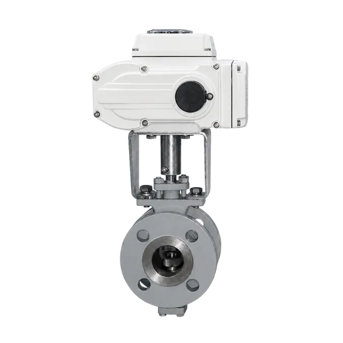
A flanged V port ball valve with electric actuator for accurate throttling, stable flow regulation and automated pipeline control in water, HVAC, chemical, energy and industrial process systems.
Related solutions: V Port Ball Valve, Electric V Port Ball Valve, Motorized V Port Ball Valve, V Notch Ball Valve, Flanged V Port Control Valve and Modulating Ball Valve.
Product Overview
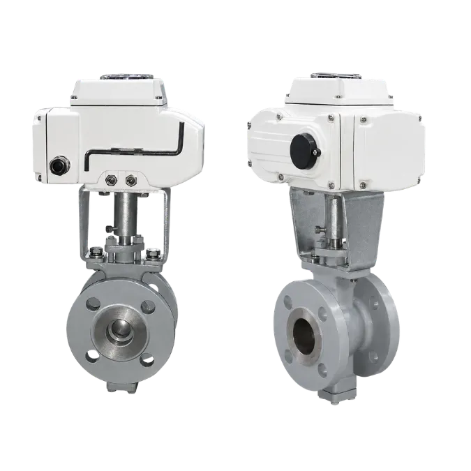
The electric actuator V port ball valve uses a specially shaped ball opening to provide more controllable flow regulation than a conventional full-port ball valve. The actuator enables remote opening, closing and proportional position control for automated process systems.
Product Advantages
The valve is designed for automated throttling duties where repeatable positioning, secure shutoff and reliable electric actuation are required.
The V-port opening changes the effective flow area progressively, supporting more stable regulation than a standard round-port ball valve.
Configure the actuator for on/off duty or modulating control with the required power supply, input signal and feedback functions.
The flanged valve body provides stable connection for industrial pipelines, equipment skids and automated process systems.
WCB, CF8, CF8M, CF3 and CF3M body options can be combined with compatible ball, stem, seal and packing materials.
Suitable for water, HVAC, chemical, energy and general process applications after confirming medium compatibility and operating conditions.
Technical Specifications
Final valve and actuator selection should be confirmed according to size, pressure, medium, temperature, control signal and required flow characteristic.
Confirm the final approved valve specification, actuator torque and control package before ordering.
Main Parts Materials
The following material data is reproduced from the supplied product catalog. Final materials should be selected according to medium, temperature, pressure and corrosion conditions.
| No. | Component | Qty | Material |
|---|---|---|---|
| 1 | Body | 1 | WCB, CF8, CF8M, CF3, CF3M |
| 2 | Ball | 1 | CF8, CF8M, hard chrome or high-velocity coating |
| 3 | After Stem | 1 | 17-4PH, SS316 |
| 4 | Cylindrical Pin | 1 | SS304, SS316 |
| 5 | Before Stem | 2 | 17-4PH, SS316 |
| 6 | Spline | 1 | 17-4PH, SS316 |
| 7 | Flat Key | 1 | SS304, 45# steel |
| 8 | After Gland | 1 | CF8, CF8M |
| 9 | O-Ring | 1 | Viton |
| 10 | Adjust Pad | 1 spare | PTFE |
| 11 | Self-Lubricating Bearing | 1 | Composite Material |
| 12 | Self-Lubricating Bearing | 1 | Composite Material |
| 13 | Packing | 1 set | PTFE |
| 14 | Gland | 1 | CF8 |
| 15 | O-Ring | 1 | Viton |
| 16 | Seal Block | 1 | PTFE, CF8, CF8M with hard chrome or high-velocity coating |
| 17 | Seal Block Spring | 1 | SS316 |
| 18 | Sealing Lid | 1 | Q235, SS304, SS316 |
| 19 | Inner Hexagon Screw | — | SS304 |
| 20 | Hexagon Screw | 4 | SS304 |
Materials are for reference. Confirm the final approved bill of materials for the selected valve configuration and operating conditions.
Technical Drawings
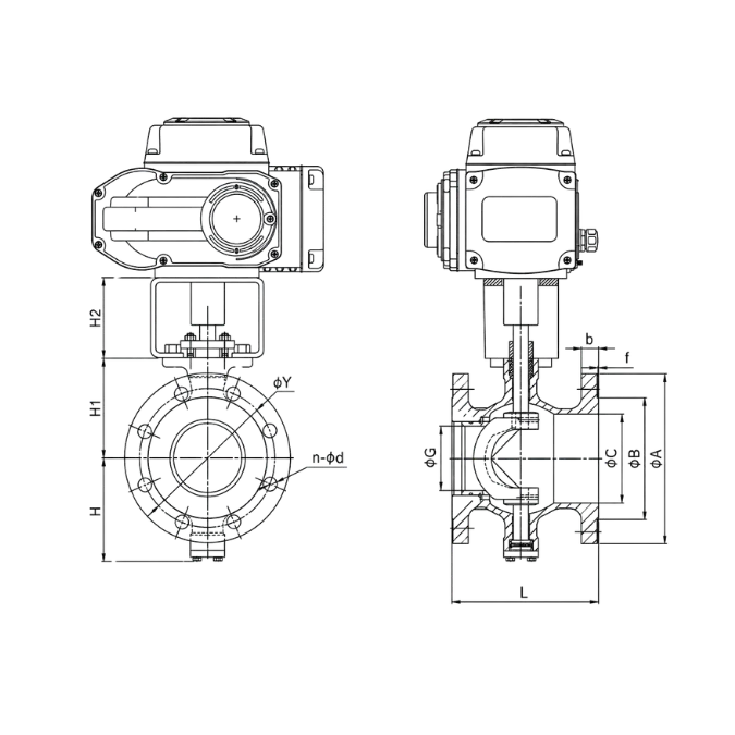
Two drawing panels are retained for product construction and dimensional reference. Replace the image URLs with your final engineering drawings.
Technical Drawing
Use the first panel for an exploded or construction drawing and the second panel for the outline and actuator dimensions.

Drawing Symbols
Refer to the PN1.6 MPa table for exact A, B, C, G, Y, b, f, L, H, H1 and H2 values.
Outline Dimensions
Reference dimensions reproduced from the supplied catalog. Values are in millimetres unless otherwise stated.
| Dimension | DN25 | DN32 | DN40 | DN50 | DN65 | DN80 | DN100 | DN125 | DN150 | DN200 |
|---|---|---|---|---|---|---|---|---|---|---|
| Inch | 1" | 1-1/4" | 1-1/2" | 2" | 2-1/2" | 3" | 4" | 5" | 6" | 8" |
| A | 115 | 140 | 150 | 165 | 185 | 200 | 220 | 250 | 285 | 340 |
| B | 65 | 76 | 84 | 99 | 118 | 132 | 156 | 184 | 211 | 266 |
| C | 38 | 45 | 50 | 62 | 73 | 90 | 115 | 134 | 164 | 206 |
| G | 20 | 25 | 32 | 40 | 55 | 62 | 80 | 100 | 125 | 155 |
| Y | 85 | 100 | 110 | 125 | 145 | 160 | 180 | 210 | 240 | 295 |
| b | 16 | 18 | 18 | 20 | 20 | 20 | 22 | 22 | 24 | 24 |
| f | 2 | 2 | 2 | 2 | 2 | 2 | 2 | 2 | 2 | 2 |
| n-φd | 4-φ14 | 4-φ18 | 4-φ18 | 4-φ18 | 8-φ18 | 8-φ18 | 8-φ18 | 8-φ18 | 8-φ22 | 12-φ22 |
| L | 102 | 102 | 114 | 124 | 145 | 165 | 194 | 194 | 229 | 243 |
| H | 81 | 86 | 90 | 93 | 108 | 123 | 138 | 128 | 170 | 200 |
| H1 | 178 | 183 | 185 | 195 | 210 | 223 | 235 | 250 | 270 | 320 |
| H2 | 28 | 30 | 30 | 26 | 28 | 31 | 33 | 25 | 31 | 31 |
Dimensions are for reference only. Confirm the final approved production drawing for the selected valve size, flange standard and actuator configuration.
Typical Applications
The valve is suitable for automated throttling and flow regulation where repeatable electric positioning and a secure flanged connection are required.

Selection Guide
Confirm the required flow characteristic, materials, pressure class and actuator control before quotation and drawing approval.
Confirm the required control characteristic and operating range for the process.
Select two-position operation for isolation or proportional control for throttling service.
Match body, ball, stem, seal and packing materials to the medium and temperature.
Confirm power supply, input signal, position feedback and communication requirements.
Provide flange standard, installation position and environmental protection requirements.
Ordering Information
Complete project data helps determine the valve body, V-port configuration, actuator torque and control package.
Send the valve size, pressure, medium, flow range, materials, actuator voltage and control requirements for a suitable quotation and drawing.