


Mixing or Diverting Service
Three-way flow arrangements support combining two inlet streams or distributing one inlet stream between two outlet paths, according to the selected valve construction.


The F-ZJHQ three-way control valve combines a three-port valve body with pneumatic diaphragm actuation for controlled mixing or diverting service. Carbon steel and stainless-steel body options, PTFE or EPDM diaphragm choices, and single- or double-acting actuator configurations support selection for compatible steam, water, air, oil and chemical process duties.
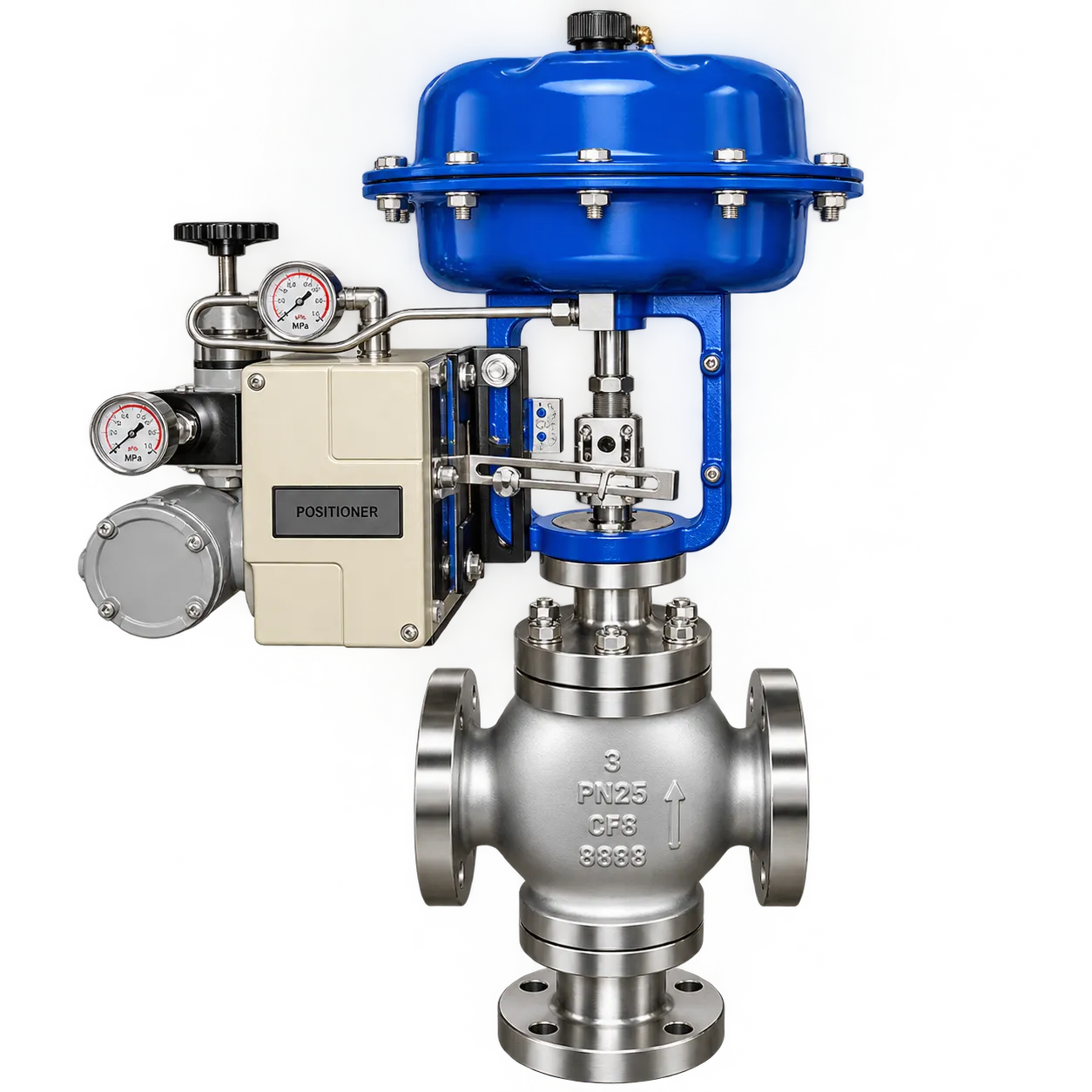
F-ZJHQ combines a three-port control valve body with pneumatic diaphragm actuation. Select the flow arrangement, body material, diaphragm material and actuator function according to the process medium and operating conditions.
Three-way flow arrangements support combining two inlet streams or distributing one inlet stream between two outlet paths, according to the selected valve construction.
Pneumatic diaphragm actuation with positioner is listed for process control. Single-acting and double-acting functions are specified in the actuator configuration data.
Body material options include carbon steel, SS304 and SS316. Material selection should reflect the process fluid, pressure, temperature and corrosion conditions.
PTFE and EPDM diaphragm options are identified in the product description. Confirm the selected diaphragm material against the operating medium and temperature.
Flanged, threaded and welded connection options can be specified according to the customer’s piping and project requirements.
Design and testing references include GB/T, IEC, ANSI, DIN, API and EN standards listed in the technical specification.
The three-way valve can be selected for mixing or diverting duty. The correct arrangement depends on the process flow direction, port designation and internal trim configuration.
Two inlet streams enter through separate ports and are combined into one common outlet. A mixing arrangement is used when a process requires blending, temperature adjustment or the combination of two compatible fluid streams.
One common inlet stream enters the valve and is directed toward two outlet paths. A diverting arrangement is used where a process needs to distribute, switch or redirect flow between two connected circuits.
The F-ZJHQ product information lists carbon steel and stainless-steel body options, together with PTFE or EPDM diaphragm options. Final material selection should be based on the process medium, concentration, working temperature and pressure.
| Selection Item | Available Options / Reference | Selection Basis |
|---|---|---|
| Valve Body | Carbon Steel / SS304 / SS316 | Process medium, pressure, temperature and corrosion conditions |
| Diaphragm | PTFE / EPDM | Fluid compatibility and operating temperature |
| Connection | Flanged / Threaded / Welded | Pipeline standard and project connection requirement |
| Flow Arrangement | Mixing / Diverting | Required inlet and outlet flow direction |
Review the nominal size, pressure and temperature range, materials, connection options and applicable standards before requesting a project quotation.
| Model | F-ZJHQ |
| Valve Type | 3-Way Pneumatic Diaphragm Control Valve |
| Size Range | DN15–DN300 (½″–12″) |
| Working Pressure Range | 0.6 MPa–6.4 MPa (6–64 bar) |
| Working Temperature Range | −20°C to +220°C (−4°F to +428°F) |
| Body Material | Carbon Steel / Stainless Steel (SS304, SS316) |
| Diaphragm Material | PTFE / EPDM |
| Connection Type | Flanged / Threaded / Welded (per customer requirement) |
| Applicable Medium | Steam, Water, Air, Oil, Corrosive Fluids, Chemical Solutions |
| Actuator Type | Pneumatic Diaphragm Actuator (with Positioner) |
| Electrical Options | 24 VDC / 110 VAC / 220 VAC (for configured electrical accessories) |
| Design Standard | GB/T 12238 / IEC 534 / ANSI B16.34 / DIN EN 1349 |
| Testing Standard | GB/T 13927 / API 598 / EN 12266-1 |
| Fire-Safe Design | Optional fire-safe construction per API 607 |
| Certification | CE / RoHS / ISO 9001 / IP65 (Actuator) |
| Customization | Special parameters and materials can be customized according to project requirements. |
The listed actuator configuration uses pneumatic diaphragm actuation with a positioner. Control accessories can be selected according to the required operating function, signal feedback and installation conditions.
| Operating Medium | Clean and dry or lubricated air, or inert gas compatible with the actuator internal parts and lubricant. |
| Operating Medium Dew Point | −20°C |
| Impurity Particle Size | No more than 30 μm; when a positioner is selected, no more than 5 μm. |
| Air Source Pressure | 3 bar to 8 bar |
| Standard Environment Temperature | −20°C to +80°C |
| Low-Temperature Type | −40°C to +80°C |
| High-Temperature Type | −20°C to +160°C |
| Lubrication | Standard type requires no additional lubricant under normal operating conditions. Special lubricants are required for low-temperature or high-temperature environments. |
| Series | AT | AW | Linear | Pneumatic Cylinder | Sanitary |
|---|---|---|---|---|---|
| Valve Body | Ball valve, butterfly valve, plug valve | Gate valve, globe valve | Knife gate valve | Sanitary butterfly valve | |
| Function | Double Acting, Single Acting (Failure Resetting FO or FC) | ||||
| Control Accessories | Solenoid Valve, Filter Regulator Lubricator (F.R.L.), Positioner, Limit Switch, Handwheel. Explosion-proof grade and signal-feedback type are available for selected solenoid valve and positioner configurations. | ||||
F-ZJHQ is designed for three-way mixing or diverting duties in industrial process lines. Typical sectors include boiler plants, thermal power generation, petrochemical facilities and metallurgy, subject to the specified pressure, temperature, medium and material compatibility.
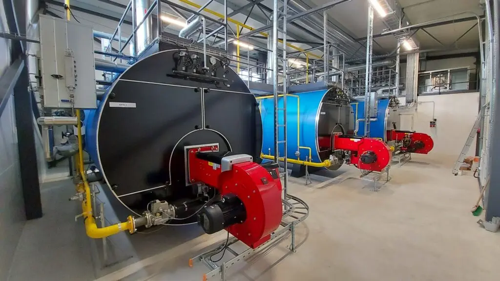
Three-way regulation in boiler steam, feedwater, condensate and auxiliary process circuits, selected for the actual operating conditions.
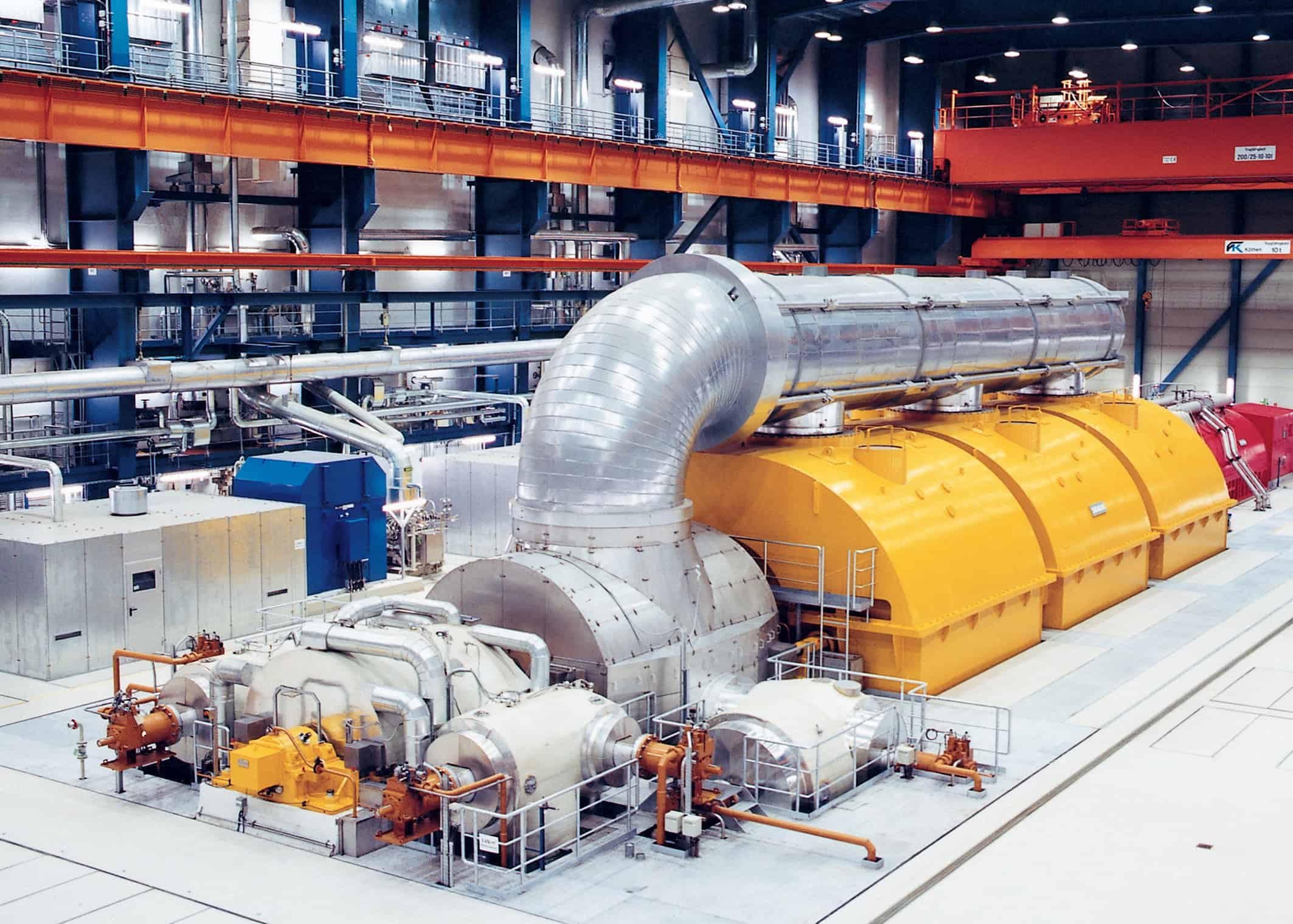
Mixing and diverting control for compatible utility and process-fluid circuits in power-generation facilities.

Flow routing and blending for compatible oil and chemical process media, based on body and trim material selection.

Three-way flow control in industrial water, oil and auxiliary process lines supporting large-scale production facilities.
Provide the process conditions and control requirements so the valve body, diaphragm material, flow arrangement, connection and pneumatic actuator can be reviewed together.
Request a QuotationConfirm medium, flow function, pressure and temperature.
Confirm size, body material, diaphragm and connection.
Specify actuator function, fail position and accessories.
Verify port designation, connection type and actuator requirements before ordering.
Common technical and purchasing questions for selecting a three-way pneumatic diaphragm control valve.
A 3-way pneumatic diaphragm control valve is used to regulate process flow through a three-port valve body. Depending on the selected configuration, it can combine two inlet streams into one outlet or divert one inlet stream between two outlets.
Mixing control combines two inlet streams into a common outlet (A + B → AB). Diverting control directs one common inlet stream toward two outlet paths (AB → A + B). The required port arrangement should be confirmed against the selected valve configuration and piping layout.
The supplied product data lists DN15–DN300 (½″–12″) and a working pressure range of 0.6 MPa–6.4 MPa (6–64 bar). Confirm the allowable pressure for the selected size, material and temperature before ordering.
The listed body material options are carbon steel, SS304 and SS316. The product description identifies PTFE and EPDM diaphragm options. Final material selection should be checked against the process medium and temperature.
The actuator reference lists double-acting and single-acting functions, with failure resetting options identified as fail-open (FO) or fail-closed (FC). The required action should be specified during quotation.
The supplied actuator data lists an air source pressure range of 3 bar to 8 bar. The operating air should be clean and dry or lubricated air, or compatible inert gas, according to the actuator requirements.
Yes. Listed control accessories include a positioner, solenoid valve, filter regulator lubricator (F.R.L.), limit switch and handwheel. Explosion-proof grade and signal-feedback types are listed as options for selected accessories.
The supplied design references are GB/T 12238, IEC 534, ANSI B16.34 and DIN EN 1349. Testing references are GB/T 13927, API 598 and EN 12266-1. Confirm the required project standard when placing an order.
Send your process medium, operating conditions and mixing or diverting requirements for product configuration review.